Clock, Alarm, GPS, Noise Generator, and Everything Else: An All-in-One Arduino Device
Building a multifunctional bedside device on Arduino Nano that combines a clock, alarm, white/pink noise generator for sleep, temperature sensor, and GPS module for automatic time synchronization.
Project Motivation
The project started with studying the effect of white and pink noise on falling asleep. I tested the effect and discovered that white noise makes it harder to concentrate. Instead of off-the-shelf solutions (mobile apps, children's devices), I decided to build my own device with a microcontroller for flexible volume and duration control.
Technical Implementation
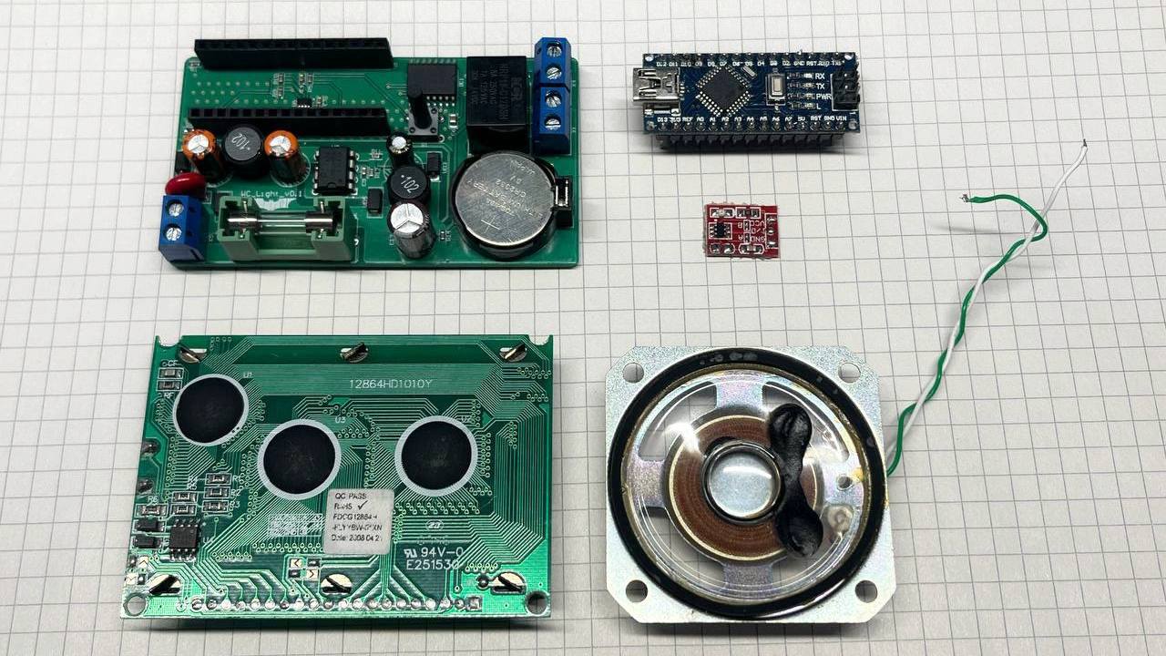
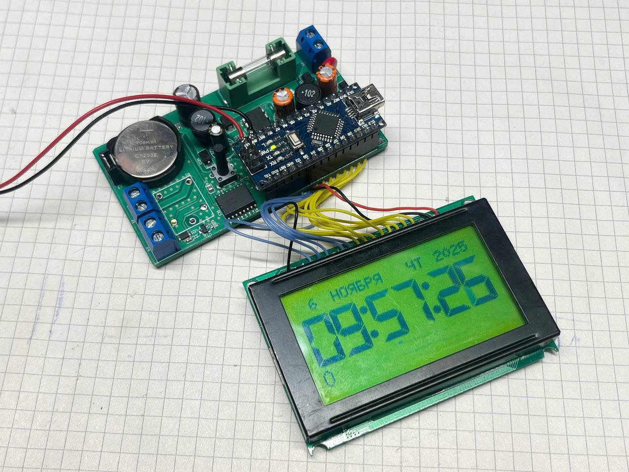
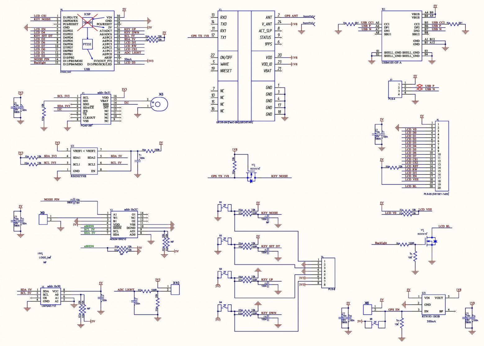
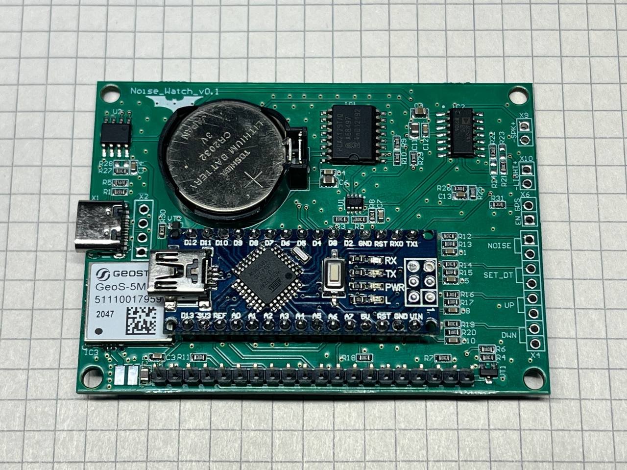
Main components:
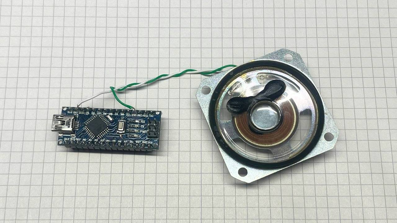
- Arduino Nano with ATmega328P microchip
- RTC (Real-Time Clock) PCA2129T for timekeeping
- LCD display 128x64 with green backlight
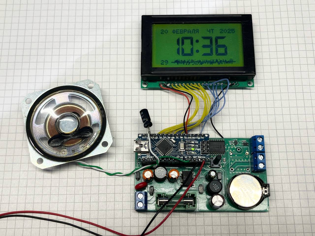
- Speaker for sound playback
- GPS module GeoS-5M
- Temperature sensor LM75
- Digital potentiometer AD5241BRZ10
- Level converter RS0302YH8
- Voltage regulator RT9193-18GB for GPS power supply
White Noise Generator
Initial attempts at simply outputting pseudorandom values proved unsuccessful. I found a working Stenzel algorithm using a Linear Feedback Shift Register (LFSR) and FIR filter for generating high-quality pink noise.
The code includes:
- A TIMER2_OVF interrupt handler
- A
stenzel_pink_sample()function for sample generation - Bit inversion lookup tables for optimization
The algorithm generates a pseudo-random sequence through an LFSR, then applies a FIR filter to shape the white noise spectrum into a pink noise (1/f) characteristic. The output is sent through a digital potentiometer (AD5241BRZ10) to control volume, then to a small speaker. The timer interrupt runs at a fixed sample rate, ensuring consistent audio output regardless of main loop activity.
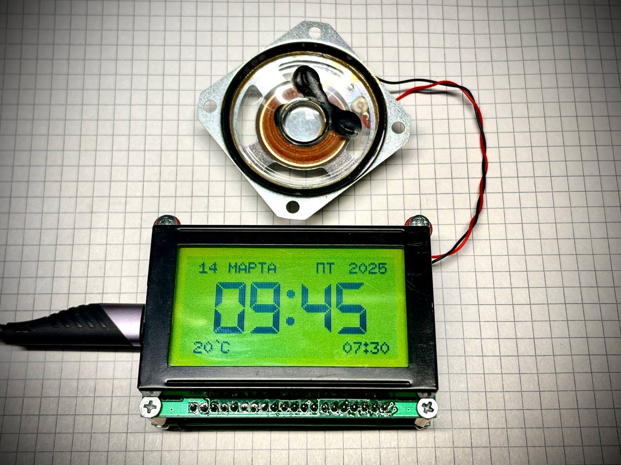
Interface and Controls
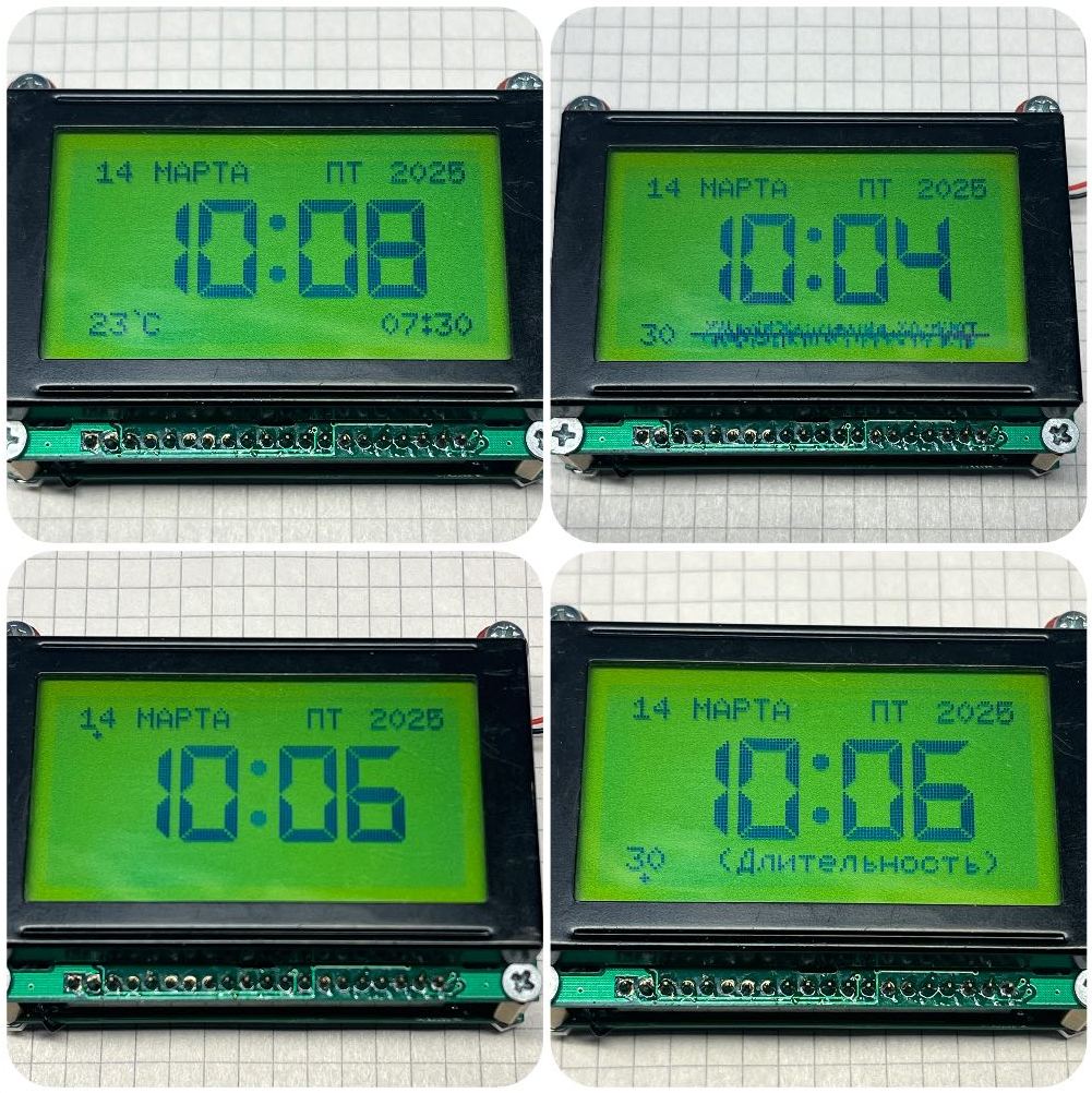
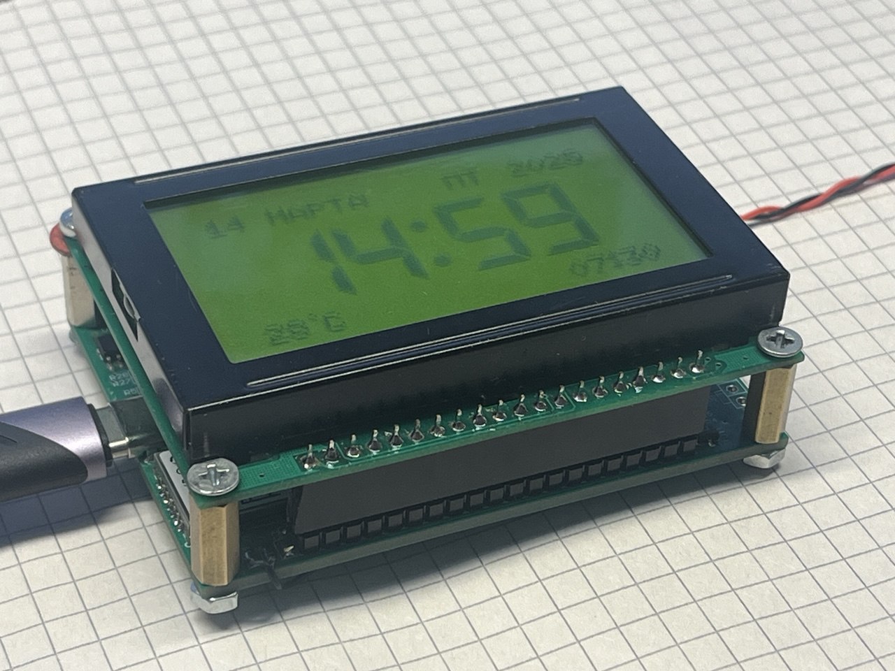
Display functionality:
- Current time display (without seconds)
- Noise generator activity visualization via a progress bar
- Countdown timer
- Temperature reading in the lower left corner
- Alarm status in the lower right corner
Control with four buttons:
- Button 1: Turn noise generator on/off
- Button 2: Enter settings mode
- Buttons 3-4: Change selected parameters
Available settings:
- Date and time
- Noise playback duration
- Volume level (via digital potentiometer)
- Backlight mode (On/Off/Auto with photoresistor)
- Temperature reading correction
- Alarm configuration
GPS Functionality
I integrated the GeoS-5M module for automatic time setting. When you simultaneously press the power button and the generator button, a waiting screen appears showing it's expecting data from the GPS receiver. This feature is still under development.
Alarm Code
if((Alarm_EN == 1) && (now.hour() == Alarm_H) && (now.minute() == Alarm_M)){
  tone(NOISE_PIN, 1000, 50);
}
The alarm emits a 1000 Hz tone for 50 milliseconds at the set time.
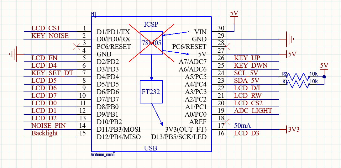
Circuit Design Decisions
- All GPIO pins on the microcontroller are occupied; ADC inputs were used for additional buttons
- The built-in LDO regulator was desoldered from the Arduino Nano board
- All buttons are duplicated to a separate connector
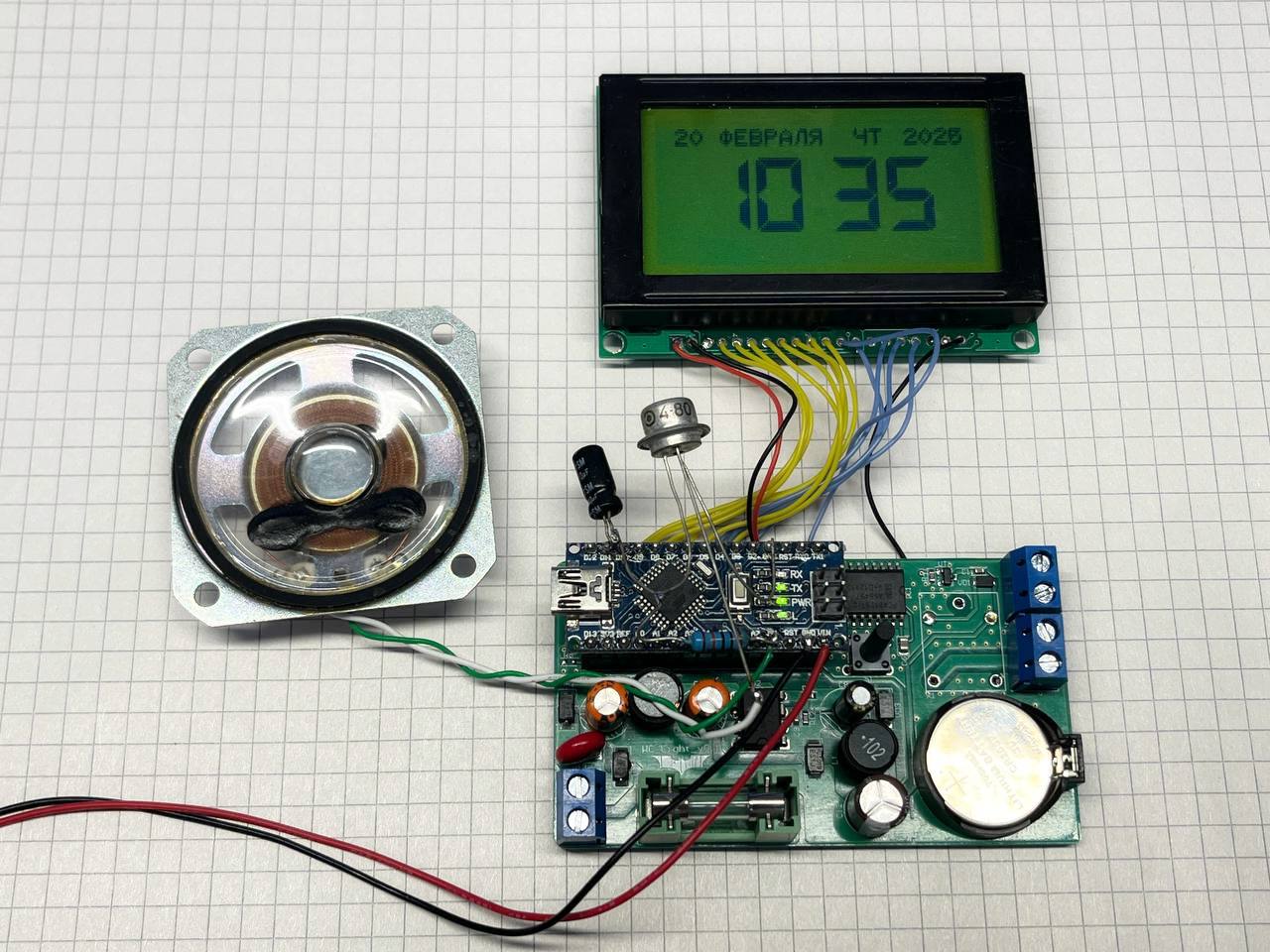
- The display is mounted on pin headers; the Arduino is soldered directly
Hardware Testing
The ATmega328P's built-in temperature sensor proved inaccurate (deviation up to 15 degrees Celsius). The LM75 sensor was chosen as a more reliable solution.
After powering on, the device worked immediately — only contrast calibration was needed.
Future Plans
I plan to create a new compact board with USB-C power, better connector placement, complete the GPS implementation, and write about the enclosure and test results in the next article.


