Creating an Emulator of the Legendary "Nu, Pogodi!" Game on Raspberry Pi Pico
A complete guide to building a hardware emulator of the iconic Soviet handheld game "Nu, Pogodi!" (based on Nintendo's Game & Watch) on the Raspberry Pi Pico, covering CPU emulation of the KB1013VK1-2 microcontroller, LCD segment rendering, PIO-based sound synthesis, and DMA-driven audio.
Introduction
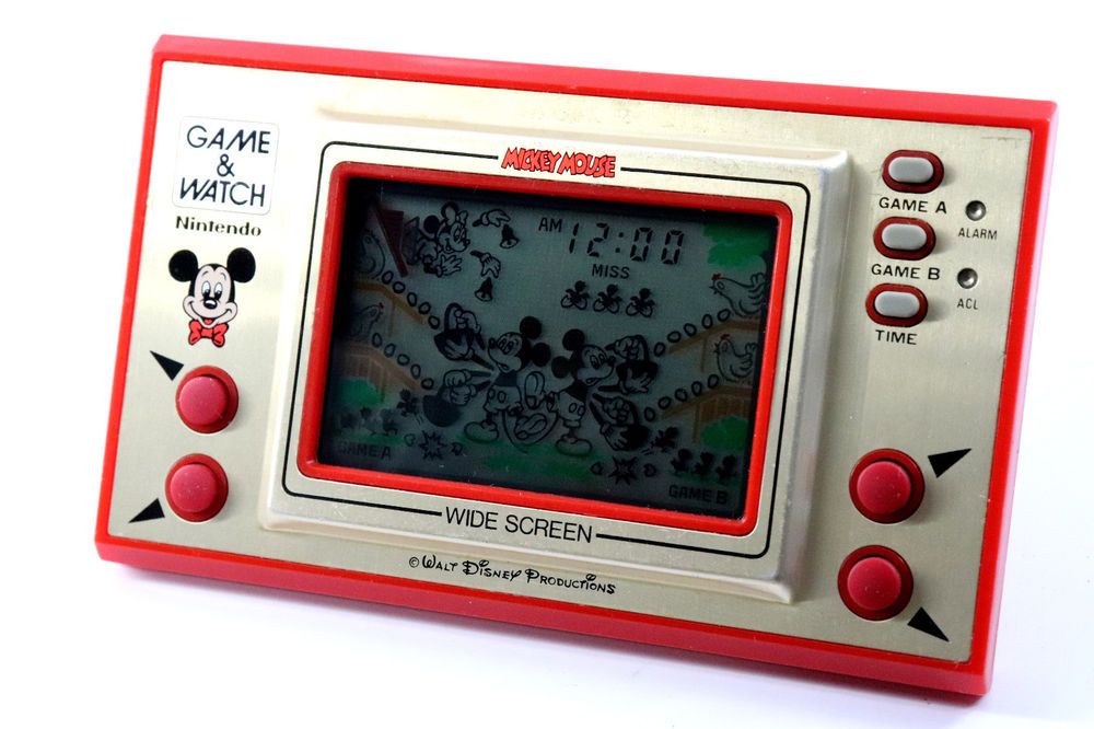
Many people over 30 who grew up in the USSR or post-Soviet countries remember the electronic game "Nu, Pogodi!" ("Well, Just You Wait!") — the iconic Soviet handheld that was a childhood staple for an entire generation. This article describes how to build a complete hardware emulator of that classic game using modern components.
The author had purchased an original unit years ago, but the LCD display had degraded beyond use. Rather than attempting a repair, the decision was made to create a full emulator on contemporary hardware. The motivation came from successfully building other microcontroller-based emulators and recognizing that accurate emulation — not mere simulation — was achievable.
Key sources consulted included existing forum discussions, debugger tools for Elektronika series games, MAME emulator code for SM-510 processors, Sharp microcontroller documentation, Soviet technical journals, and various GitHub projects related to LCD game emulation.
Historical Context
Nintendo released its Game & Watch series in 1981. The Soviet Union responded with clones, most notably the Elektronika IM-02 "Nu, Pogodi!" — based on the "Egg" variant (known as "EG-26" in Nintendo's lineup) but featuring the famous Soviet cartoon character Wolf catching eggs instead of the original's generic characters.
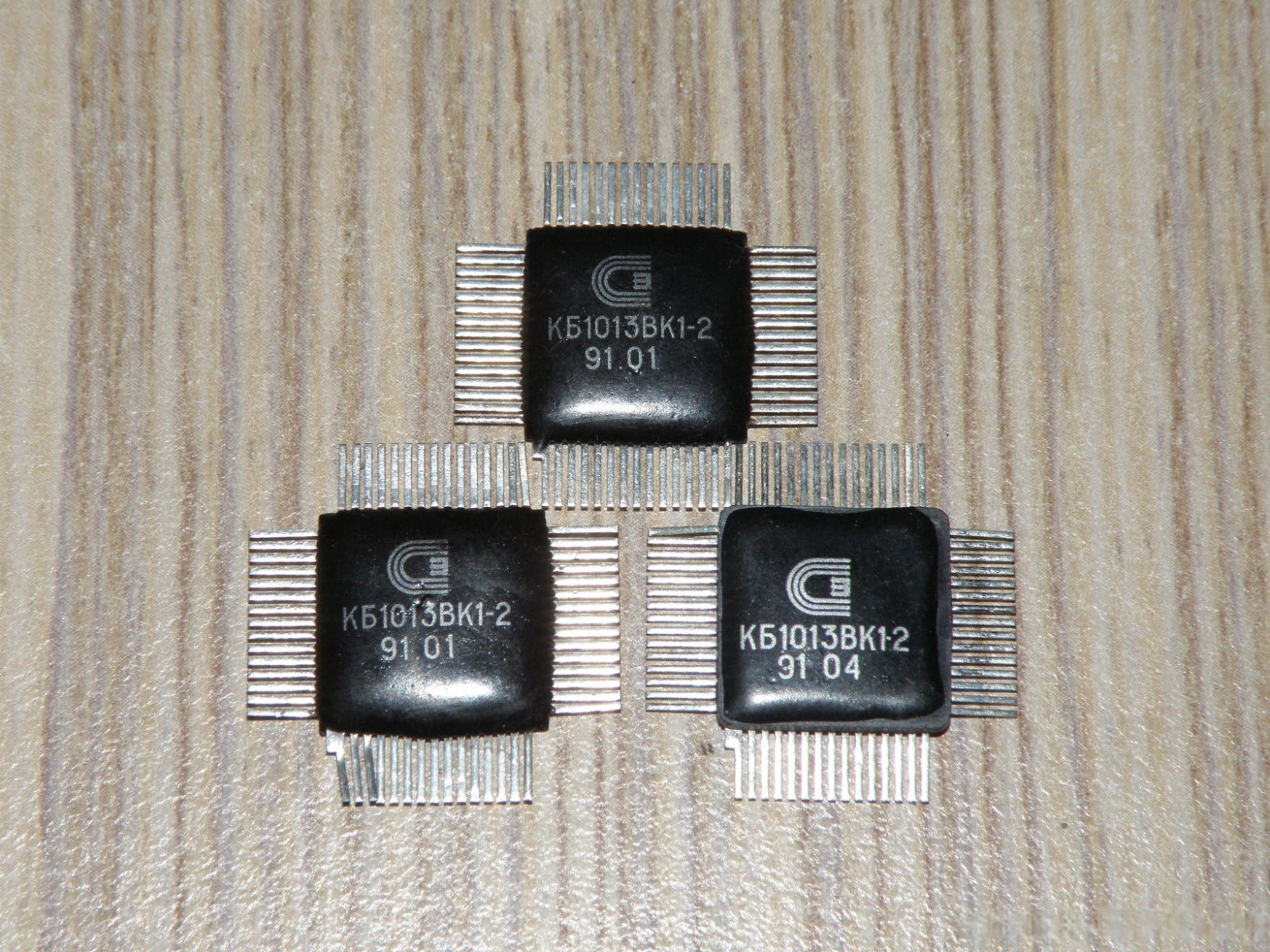
The core microcontroller used was the KB1013VK1-2, a Soviet equivalent to the Japanese Sharp SM-5A processor.
How "Nu, Pogodi!" Works
The game hardware consists of:
- PCB with KB1013VK1-2 microcontroller
- Segment LCD display (IZhM2-71-01 or IZhM13-71)
- Piezo speaker
- 32,768 Hz crystal oscillator
- Membrane buttons organized as a 2x4 matrix
- Conductive rubber pads
- Polarizing filters and reflective film
Microcontroller Architecture: KB1013VK1-2 / SM-5A
Key characteristics of the processor:
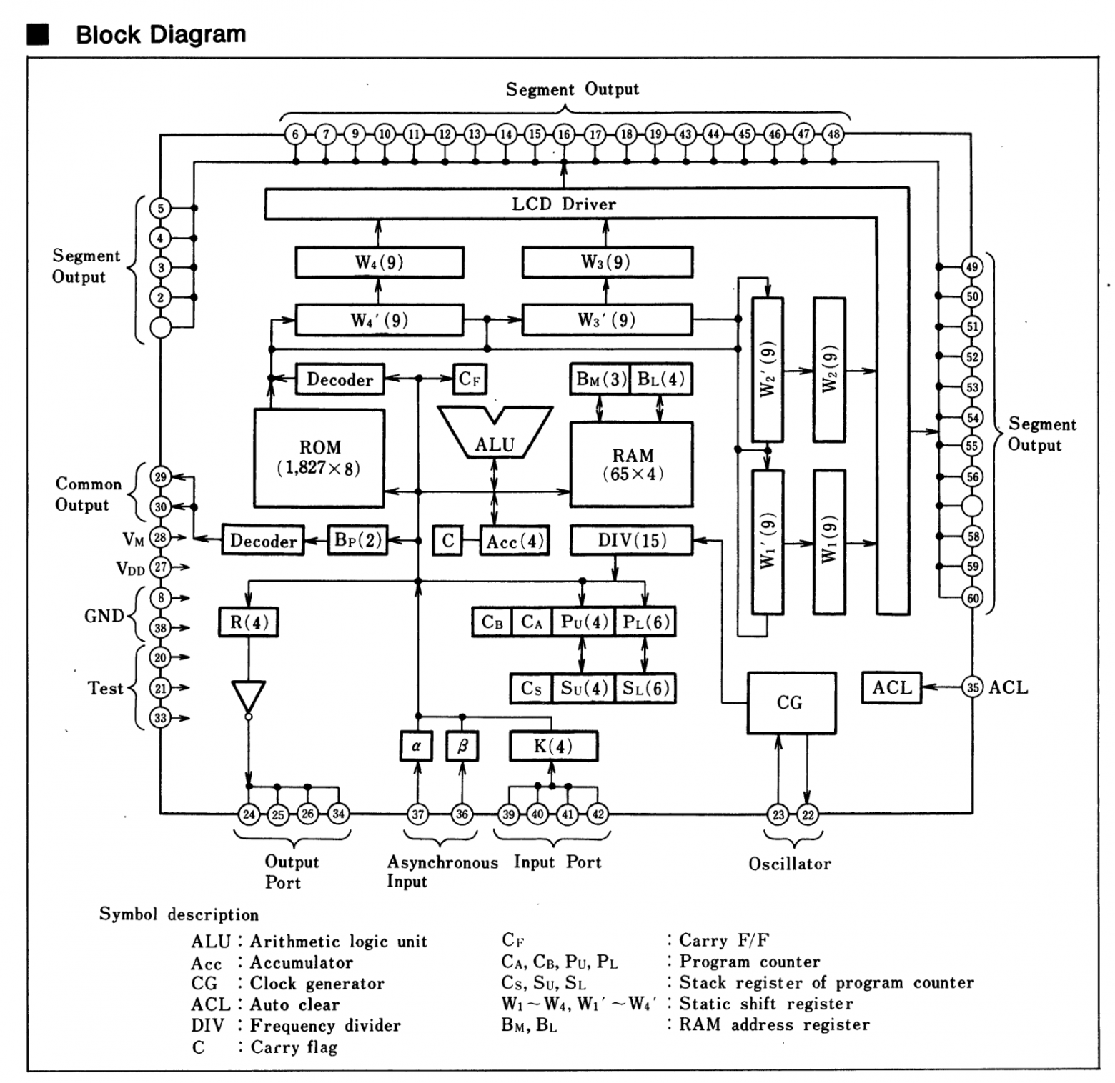
- Harvard architecture with separate program and data memory buses
- 4-bit accumulator (Acc)
- 11-bit program counter (PC) using polynomial feedback
- Programmable timer (15-bit, with 4-bit accessible portion)
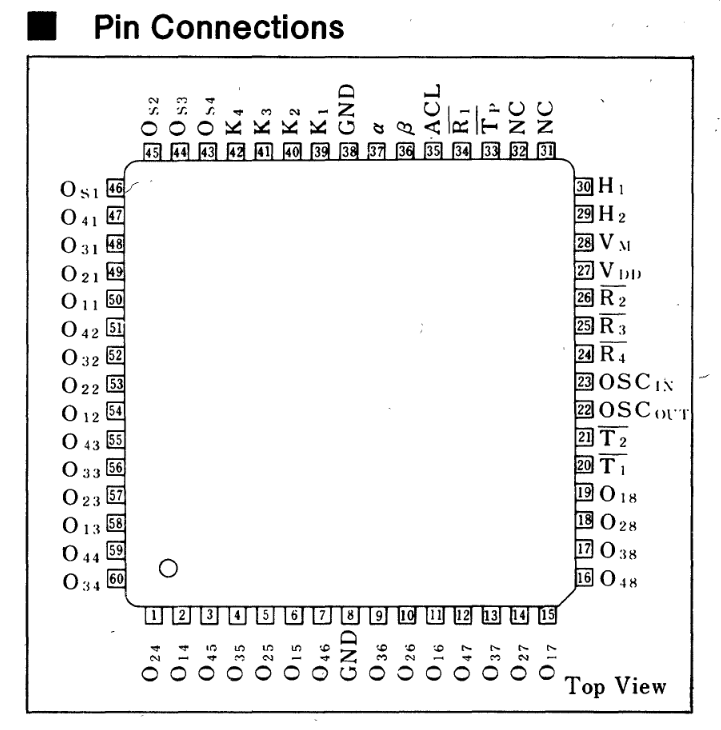
- LCD driver controller with 36-bit output registers
- Matrix keyboard support through input/output ports
- Mask ROM — firmware cannot be modified after manufacturing
- 58 basic instructions, mostly single-byte
Unlike modern processors, the KB1013VK1-2 uses "pull-based" interrupts rather than "push-based." The program must explicitly poll interrupt flags (INT1 and INT2) rather than receiving automatic hardware interrupts. This is a significant architectural difference that affects how the emulator must handle timing.
LCD Display Technology
Segment LCD displays operate through polarization. Two polarizing films oriented perpendicular to each other create darkness unless liquid crystals between them properly rotate the light. When voltage is applied, the electric field aligns the crystals, blocking light transmission and darkening the segment.
The display requires alternating voltage (never DC) to prevent crystal degradation. The microcontroller's built-in LCD driver handles the timing and multiplexing of display segments across common lines.
Building the Emulator
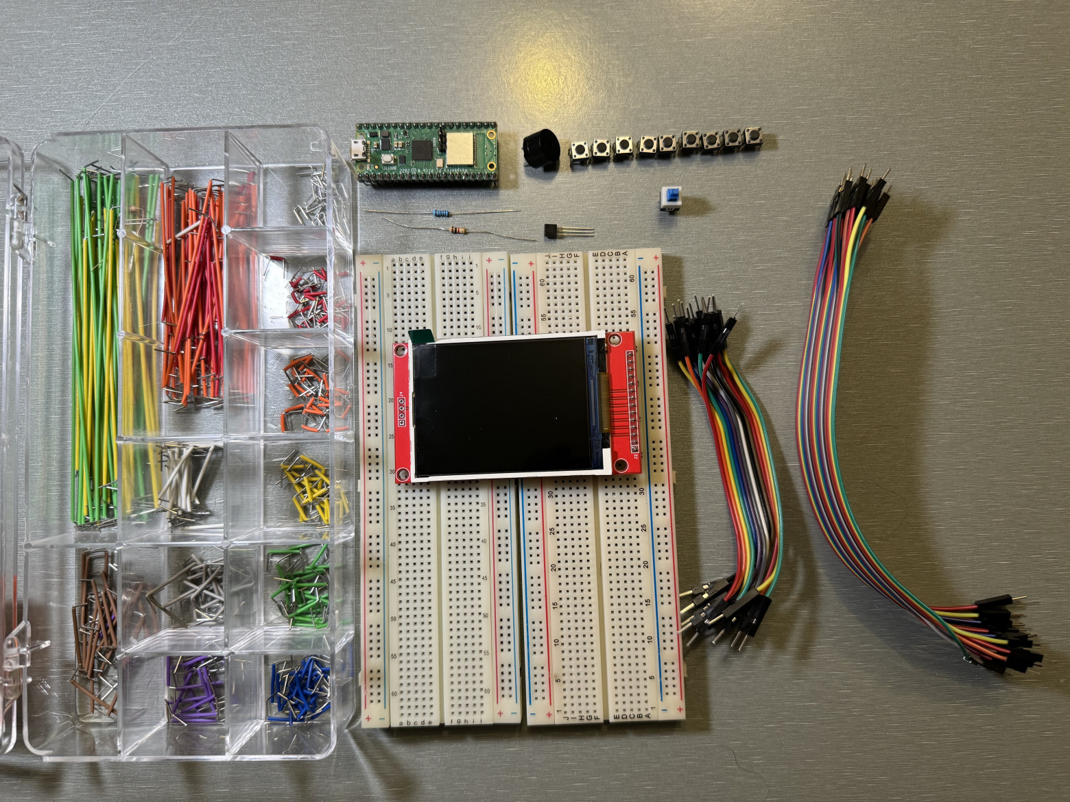
Required hardware:
- Raspberry Pi Pico (or compatible RP2040 board)
- Breadboard
- 8 tactile buttons
- TFT display with ILI9341 driver
- Passive buzzer
- Resistors: 100 ohm, 1K ohm
- 2N2222 transistor
- Dupont/jumper wires
Wiring Diagram
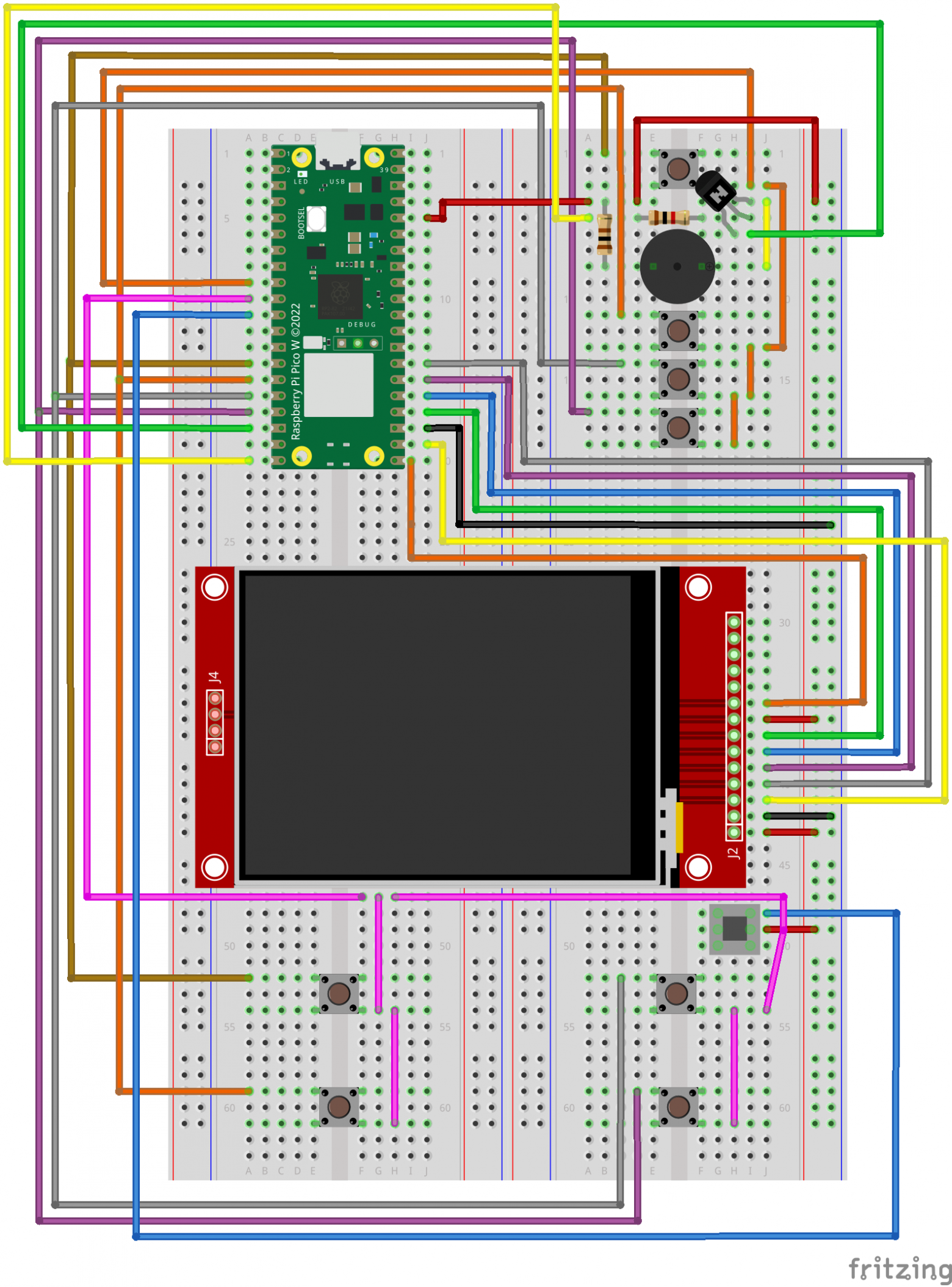
Raspberry Pi Pico to TFT Display (MSP2806):
PIN21 GP16 (SPI0 RX)  -> SDO (MISO)
PIN24 GP18 (SPI0 SCK) -> SCK
PIN25 GP19 (SPI0 TX)  -> SDI (MOSI)
PIN26 GP20            -> RESET
PIN27 GP21            -> DC
PIN22 GP17 (SPI0 CSn) -> CS
PIN36 3V3(OUT)        -> VCC, LED
PIN23 GND             -> GND
Button Matrix:
PIN9  GP6  -> Alarm, Game A, Game B, Time
PIN10 GP7  -> Arrow buttons (diagonal and straight)
PIN14 GP10 -> upper-left / Alarm
PIN15 GP11 -> lower-left / Game A
PIN16 GP12 -> upper-right / Game B
PIN17 GP13 -> lower-right / Time
Buzzer Module:
PIN36 3V3(OUT) -> VCC
PIN18 GND      -> GND
PIN20 GP15     -> I/O (with current-limiting resistor)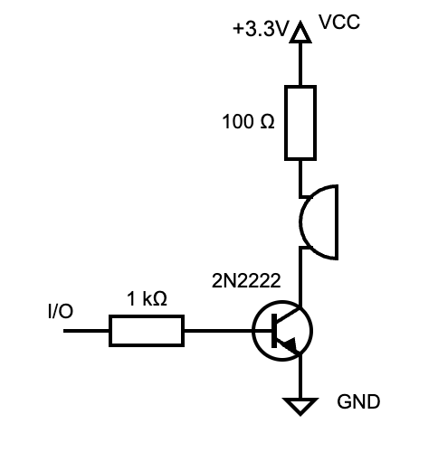
CPU Emulation Implementation
The emulator implements a standard fetch-decode-execute cycle processing approximately 2 clock cycles per instruction:
void device_run() {
  int remaining_icount = m_icount;

  while (m_icount > 0) {
    m_icount--;

    if (m_halt && !wake_me_up()) {
      div_timer(remaining_icount);
      m_icount = 0;
      return;
    }

    m_prev_op = m_op;
    m_prev_pc = m_pc;
    m_op = read_byte_program(m_pc);

    increment_pc();
    get_opcode_param();

    if (m_skip) {
      m_skip = false;
      m_op = 0;
    } else
      execute_one();

    div_timer(remaining_icount - m_icount);
    remaining_icount = m_icount;
  }
}
LCD Display Emulation
The display emulation divides the TFT screen into zones corresponding to the original LCD segments. Depending on the state of the output registers (O/W ports), segments are rendered or hidden. Background artwork overlays the segment pattern, recreating the original game's visual appearance.
The original game updates at 60 Hz. The Pico emulation achieves acceptable performance despite slightly lower frame rates. Flicker mitigation accounts for the LCD inertia that was present in the original hardware — segments don't disappear instantly, matching the slightly "ghosting" behavior players remember.
Sound Synthesis
The original game produces simple 1-bit sound through square wave generation. The emulator uses the Raspberry Pi Pico's PIO (Programmable Input/Output) state machine for precise timing:
.program beeper_tx

.wrap_target
out pins, 1 [7]
.wrap
This PIO program outputs one bit per 8 execution cycles, creating accurate audio timing. Two DMA (Direct Memory Access) buffers swap roles — one plays while the other records — ensuring continuous sound output without gaps.
DMA Configuration:
dma_channel_config c1 = dma_channel_get_default_config(dma_chan1);
channel_config_set_transfer_data_size(&c1, DMA_SIZE_8);
channel_config_set_read_increment(&c1, true);
channel_config_set_write_increment(&c1, false);
channel_config_set_dreq(&c1, DREQ_PIO0_TX0);
channel_config_set_ring(&c1, false, 8);
channel_config_set_chain_to(&c1, dma_chan2);
The author discovered cache issues when accessing both program code and ROM data from external flash memory. The solution: place all executable code in RAM while keeping the ROM image in flash, with explicit memory region declarations to prevent cache invalidation during sound generation.
Synchronization: CPU, Audio, and Display
The RP2040's dual cores enable true parallel execution:
- Core 0: Display emulation (rendering segments to the TFT)
- Core 1: CPU emulation (running the game logic)
DMA interrupts trigger display updates approximately every 8 buffer cycles, maintaining synchronization between audio playback and visual updates.
Button Handling
The game uses a 2x4 button matrix. The emulator replicates this exact structure for authentic behavior. Matrix scanning occurs during game loop iterations, matching the original hardware's polling approach.
Building and Deployment
# 1. Install dependencies
sudo apt install cmake python3 build-essential gcc-arm-none-eabi \
  libnewlib-arm-none-eabi libstdc++-arm-none-eabi-newlib

# 2. Create workspace
cd ~
mkdir emulator && cd emulator

# 3. Clone Pico SDK
git clone https://github.com/raspberrypi/pico-sdk
cd pico-sdk
git submodule update --init --recursive

# 4. Clone emulator repository
cd ..
git clone https://github.com/artyomsoft/pico-nu-pogodi.git
cd pico-nu-pogodi
git submodule update --init --recursive

# 5. Build
export PICO_SDK_PATH=$(pwd)/../pico-sdk
mkdir -p build
cd build
cmake .. -DPICO_COPY_TO_RAM=1
make

# 6. Upload pico_nupogodi.uf2 to Pico in bootloader mode
Pre-built binaries are available on the GitHub releases page.
Bonus: Infinite Lives Mode
The original game includes a debugging feature: applying a logic-high signal to the first interrupt input disables penalty scoring. The emulator implements this via an optional button, allowing infinite play without losing lives.
This feature allowed the author to confirm a long-standing rumor: there is no hidden cartoon easter egg at 1,000 points. The game simply continues with increasing difficulty.
Final Result
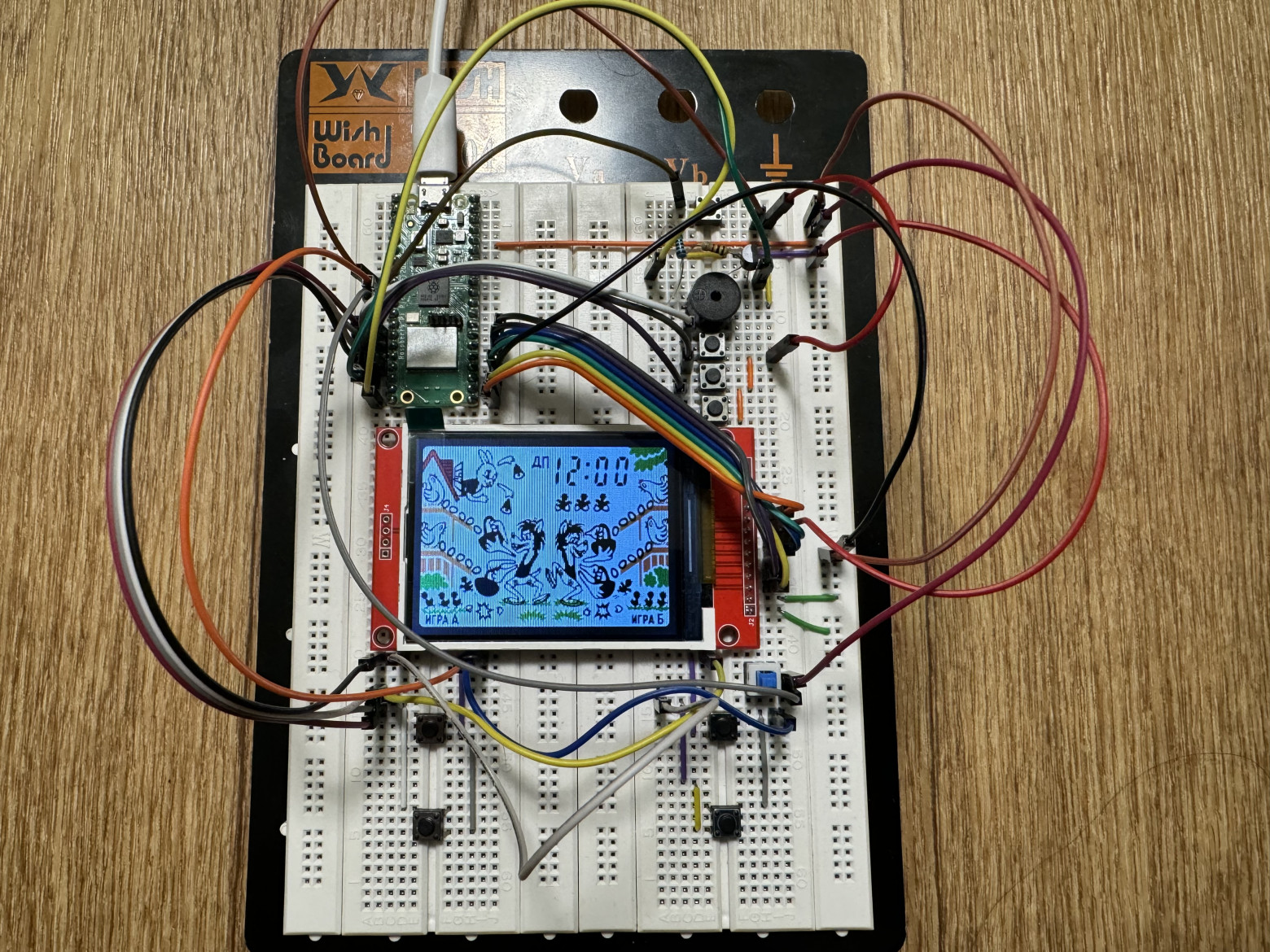
The completed emulator faithfully reproduces the original game's behavior. Despite using a breadboard prototype rather than a custom PCB, the device provides an authentic gameplay experience through accurate hardware emulation.
Key Learnings
- 1980s microcontroller design remains elegant despite severe resource constraints
- Harvard architecture simplifies emulator development by separating code and data
- PIO state machines on the RP2040 enable precise low-level I/O control impossible with standard GPIO
- DMA chaining solves audio synchronization challenges without CPU overhead
- Flash memory caching requires careful management for real-time audio applications
References
Conclusion
The project demonstrates that sophisticated hardware emulation remains achievable on modest modern platforms. The original game's 1,856 bytes of ROM contained a complete, engaging experience that remains playable decades later — a testament to the efficiency of 1980s programming. The emulator serves not just as a nostalgia piece, but as a practical teaching tool for microcontroller architecture and embedded systems design.


