Building a DIY Active Noise Cancellation System for an Urban Apartment
A deep dive into building a microcontroller-based active noise cancellation system for urban apartments, covering the physics of destructive interference, analog approaches, and a complete ESP32 implementation with code.
Active noise cancellation technology has been around since the 1930s, yet it remains almost exclusively confined to headphones and aviation headsets. What if we could apply the same principle to an entire room — specifically, to reduce the constant low-frequency rumble of urban traffic in a city apartment? This article explores exactly that: building a DIY active noise cancellation (ANC) system using affordable microcontroller components.

A Brief History of Active Noise Cancellation
In the 1930s, physicist Paul Lueg proposed the first active noise cancellation system for factory ventilation ducts. The idea was elegant: generate an "anti-sound" — an acoustic wave that is the exact phase-inverted copy of the unwanted noise — so that when the two waves meet, they undergo destructive interference and cancel each other out.
The concept moved from theory to practice through aviation in the 1950s, where engine noise in cockpits made ANC a practical necessity. Bose released the first commercial ANC headphones in 1986, and by the 1990s, the technology had reached widespread consumer adoption.
But room-scale ANC has remained an unsolved problem, primarily because the physics become vastly more complex when you move from the controlled environment inside an ear cup to an open three-dimensional space.
Approach 1: Analog Phase Shifter
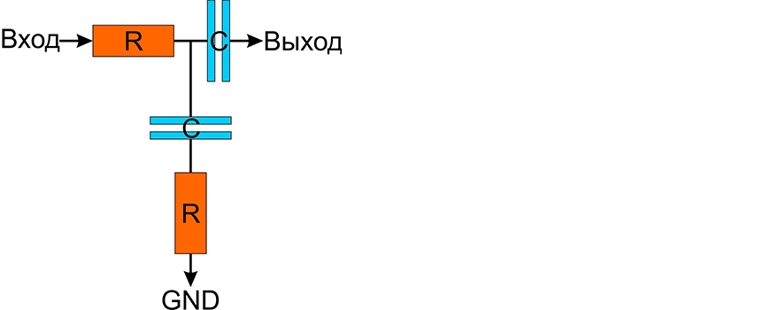
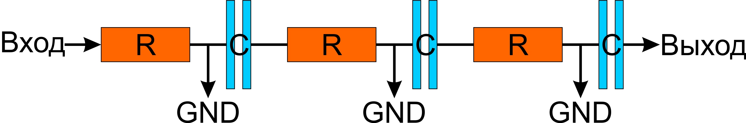
The simplest approach uses resistor-capacitor (RC) networks to create a 180-degree phase shift at a target frequency. By cascading three RC stages, you can achieve the required phase inversion.
The frequency at which a three-stage RC network produces a 180-degree phase shift is given by:
f = 1 / (2 * pi * R * C * sqrt(6))
However, these analog devices have severe limitations: they are too rigidly fixed to a single frequency, and they significantly attenuate the signal amplitude by a factor of 5 to 10. In practice, this means the anti-noise signal is far too weak to effectively cancel the original noise, and it only works at one specific frequency.
Approach 2: Microcontroller-Based Intelligent System
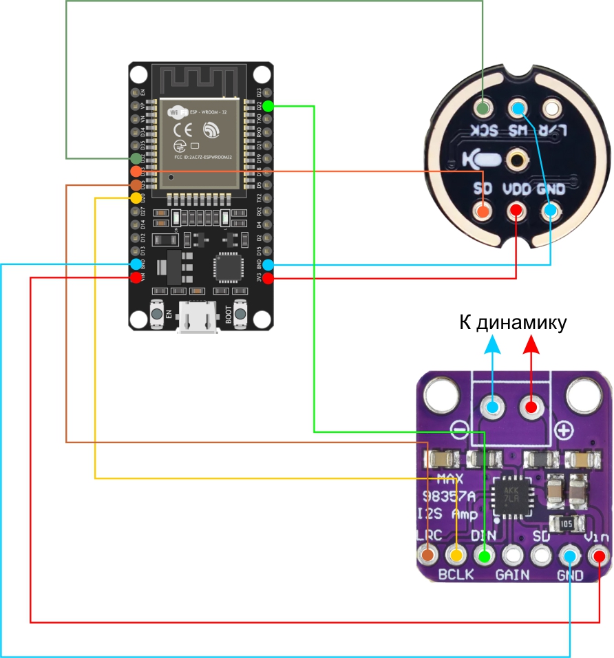
A far more promising approach uses a microcontroller to digitally analyze incoming noise and generate the appropriate anti-noise signal in real time. The proposed system uses:
- ESP32 microcontroller — dual-core, 240 MHz, with built-in I2S support
- INMP441 digital MEMS microphone — frequency range 50 Hz to 15 kHz, I2S interface
- MAX98357 digital I2S amplifier — 3.2W output, no DAC required
- Standard 4-8 ohm speaker
Expected Performance
- Approximately 80% noise reduction near roadways
- Up to 90% reduction in office environments with consistent noise sources
- Most effective for low-frequency urban noise in the 50–500 Hz range
Processing Constraints
The ESP32's 240 MHz processor provides 1–2 ms of processing latency. This is sufficient for frequencies up to approximately 500 Hz, but inadequate for higher frequencies such as bird chirps or car horns. For urban apartment noise — which is dominated by traffic rumble, HVAC systems, and building vibrations — this frequency range covers the most problematic sounds.
Complete Source Code
Here is the full Arduino-compatible implementation:
//Developed with assistance from DeepSeek
//Code provided without any guarantees of proper operation
#include <driver/i2s.h>

// I2S pin configuration
#define MIC_DATA_PIN   33  // INMP441 DATA
#define MIC_CLOCK_PIN  32  // INMP441 SCK (unused but must be connected)
#define I2S_BCLK_PIN   26  // BCLK for MAX98357
#define I2S_LRC_PIN    25  // LRCLK for MAX98357
#define I2S_DOUT_PIN   22  // DATA for MAX98357

// Processing parameters
const int SAMPLE_RATE = 44100;  // Sampling frequency (Hz)
const int BUFFER_SIZE = 512;    // Buffer size
const int TARGET_LOW_FREQ = 50; // Minimum noise frequency (Hz)
const int TARGET_HIGH_FREQ = 500; // Maximum noise frequency (Hz)

// Global variables
float noiseAmplitude = 0.0;    // Noise amplitude
float targetFrequency = 100.0; // Dominant noise frequency

// I2S initialization
void setupI2S() {
  i2s_config_t i2sConfig = {
    .mode = (i2s_mode_t)(I2S_MODE_MASTER | I2S_MODE_RX | I2S_MODE_TX),
    .sample_rate = SAMPLE_RATE,
    .bits_per_sample = I2S_BITS_PER_SAMPLE_16BIT,
    .channel_format = I2S_CHANNEL_FMT_ONLY_LEFT,
    .communication_format = I2S_COMM_FORMAT_I2S,
    .intr_alloc_flags = ESP_INTR_FLAG_LEVEL1,
    .dma_buf_count = 4,
    .dma_buf_len = BUFFER_SIZE
  };

  i2s_pin_config_t pinConfig = {
    .bck_io_num = I2S_BCLK_PIN,
    .ws_io_num = I2S_LRC_PIN,
    .data_out_num = I2S_DOUT_PIN,
    .data_in_num = MIC_DATA_PIN
  };

  i2s_driver_install(I2S_NUM_0, &i2sConfig, 0, NULL);
  i2s_set_pin(I2S_NUM_0, &pinConfig);
}

// Noise analysis (simplified FFT)
void analyzeNoise(int16_t* samples) {
  float maxAmplitude = 0;
  for (int i = TARGET_LOW_FREQ * BUFFER_SIZE / SAMPLE_RATE;
       i < TARGET_HIGH_FREQ * BUFFER_SIZE / SAMPLE_RATE; i++) {
    if (abs(samples[i]) > maxAmplitude) {
      maxAmplitude = abs(samples[i]);
      targetFrequency = (float)i * SAMPLE_RATE / BUFFER_SIZE;
    }
  }
  noiseAmplitude = maxAmplitude / 32768.0; // Normalization
}

// Anti-noise generation
void generateAntiNoise(int16_t* outputBuffer) {
  static float phase = 0.0;
  float phaseIncrement = 2 * PI * targetFrequency / SAMPLE_RATE;

  for (int i = 0; i < BUFFER_SIZE; i++) {
    outputBuffer[i] = (int16_t)(noiseAmplitude * 32767 * sin(phase + PI)); // +PI for phase inversion
    phase += phaseIncrement;
    if (phase > 2 * PI) phase -= 2 * PI;
  }
}

void setup() {
  Serial.begin(115200);
  setupI2S();
}

void loop() {
  int16_t inputSamples[BUFFER_SIZE];
  int16_t outputSamples[BUFFER_SIZE];
  size_t bytesRead;

  // Read data from microphone
  i2s_read(I2S_NUM_0, &inputSamples, BUFFER_SIZE * sizeof(int16_t), &bytesRead, portMAX_DELAY);

  // Analyze and generate anti-noise
  analyzeNoise(inputSamples);
  generateAntiNoise(outputSamples);

  // Play anti-noise
  i2s_write(I2S_NUM_0, &outputSamples, BUFFER_SIZE * sizeof(int16_t), &bytesRead, portMAX_DELAY);

  // Logging (can be disabled)
  static uint32_t lastLogTime = 0;
  if (millis() - lastLogTime > 1000) {
    Serial.printf("Dominant noise: %.0f Hz, Amplitude: %.2f\n", targetFrequency, noiseAmplitude);
    lastLogTime = millis();
  }
}
The code performs automatic dominant frequency detection within the 50–500 Hz range and generates a phase-inverted sine wave at that frequency through the speaker.
Speaker Placement Options
Option 1: Microphone at the window, speaker directed at the listener. The microphone captures incoming noise at the window, and the speaker produces anti-noise near the listener's position. This creates a localized zone of quiet — effective for a specific seating position but limited in coverage.
Option 2: Microphone near the listener, speaker at the window. The anti-noise meets the incoming sound at its source (the window), potentially creating a broader quiet zone. However, this requires precise calibration of the delay to account for the distance between speaker and window.

Alternative: Vibration Speaker on Glass
An innovative alternative is to use a vibration speaker (exciter) attached directly to the window glass. This effectively converts the entire window pane into a massive speaker diaphragm. The advantage is that the anti-noise is generated at exactly the same surface through which the noise enters, which could improve cancellation effectiveness. The disadvantage is that window glass has its own resonance characteristics that may distort the anti-noise signal.
Important Limitations
No existing active noise cancellation system can provide 100% silence. These systems are designed to suppress sound rather than eliminate it entirely. The achievable reduction depends on:
- The consistency of the noise source (steady rumble is easier to cancel than random sounds)
- The distance between the microphone, speaker, and noise source
- Processing latency relative to the target frequency
- Room acoustics and reflections
For urban apartment noise dominated by low-frequency traffic rumble, a well-tuned system can make a meaningful difference in comfort — reducing the constant background drone that is both annoying and, over time, harmful to health.
FAQ
What is this article about in one sentence?
This article explains the core idea in practical terms and focuses on what you can apply in real work.
Who is this article for?
It is written for engineers, technical leaders, and curious readers who want a clear, implementation-focused explanation.
What should I read next?
Use the related articles below to continue with closely connected topics and concrete examples.