DIY Gas Discharge Lamp with Custom Symbols
A detailed guide on building a large decorative gas discharge vacuum tube from scratch, featuring hand-cut Cyrillic letter electrodes that glow in argon gas, using recycled fluorescent lamp glass and a titanium getter electrode.
This article describes the creation of a large decorative electronic vacuum device (EVD) — a practical, large-scale decorative-souvenir vacuum tube, an evolution of a prototype with argon filling. The device uses recycled glass from fluorescent lamps and a titanium getter electrode.
1. Glass: Preparation and Properties
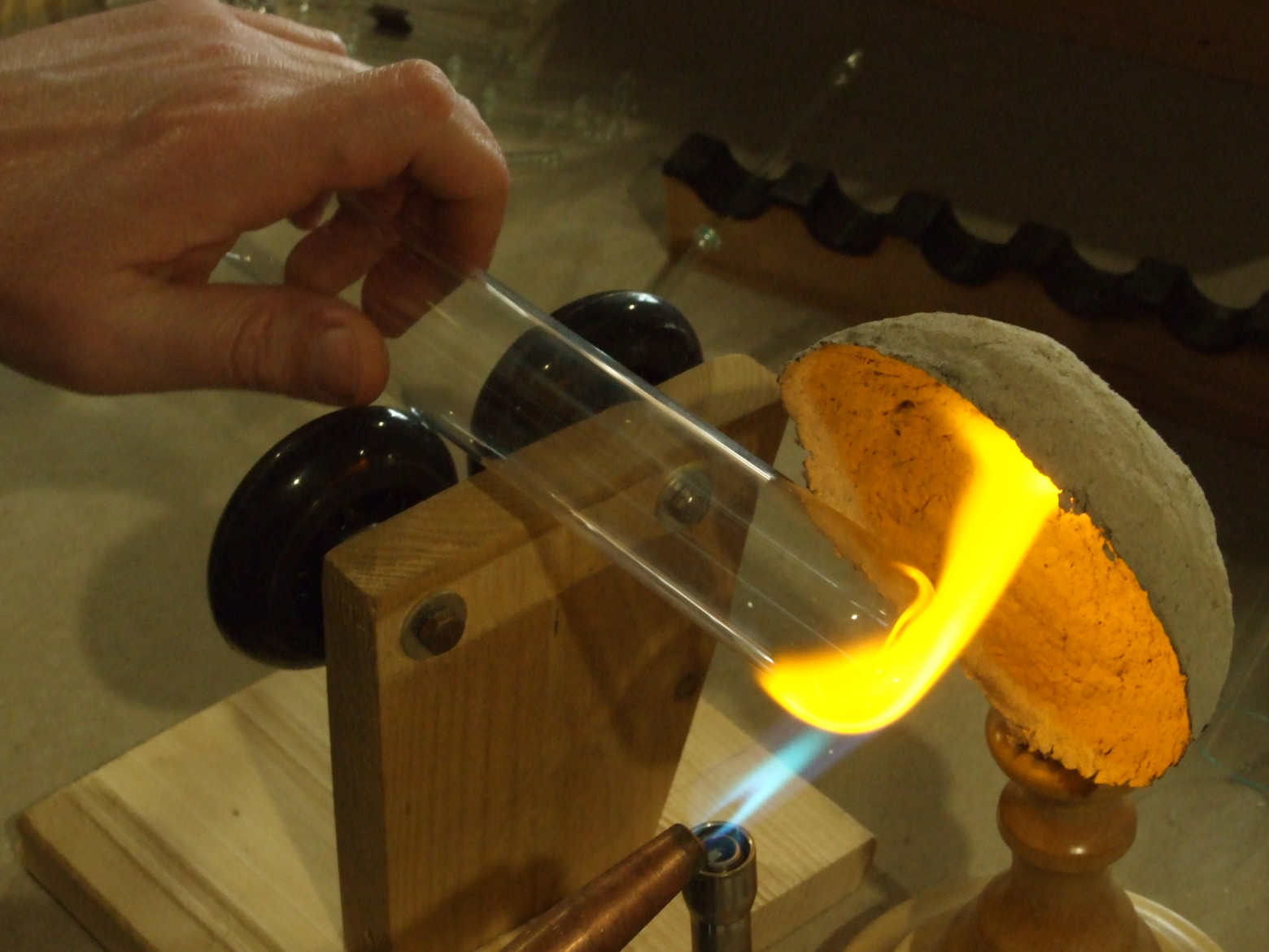
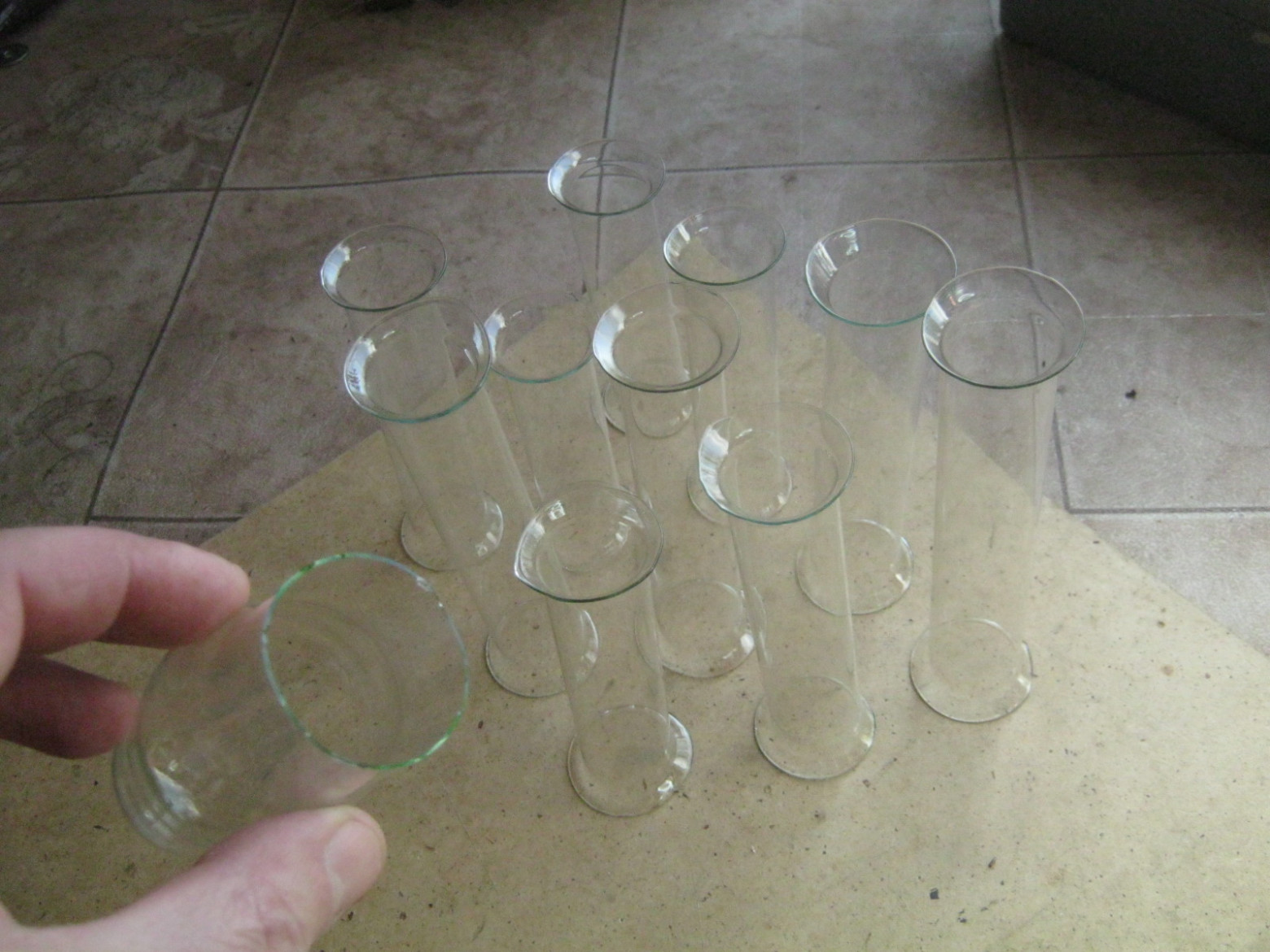
The glass used comes from fluorescent lamp tubes of T12 and T8 sizes, belonging to the platinum glass group. These glasses are inexpensive and widely available, low-melting, do not darken in a reducing gas-air flame, and have a green or bluish tint at the edge. The special bimetal platinite (used for electrical leads in vacuum devices) seals into them easily and reliably. However, platinum glass has a high coefficient of thermal expansion (CTE) and is prone to cracking during heating or cooling.
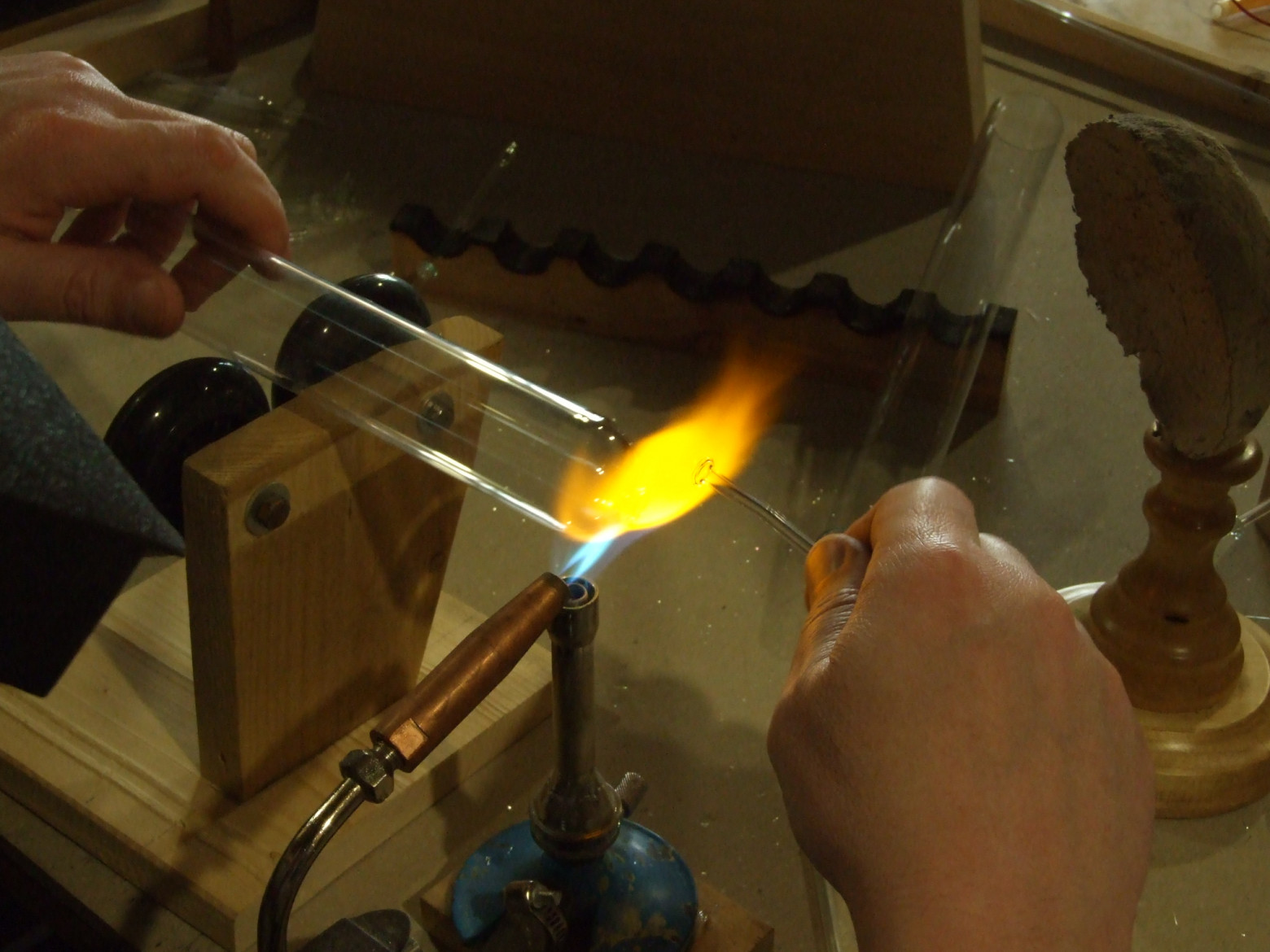
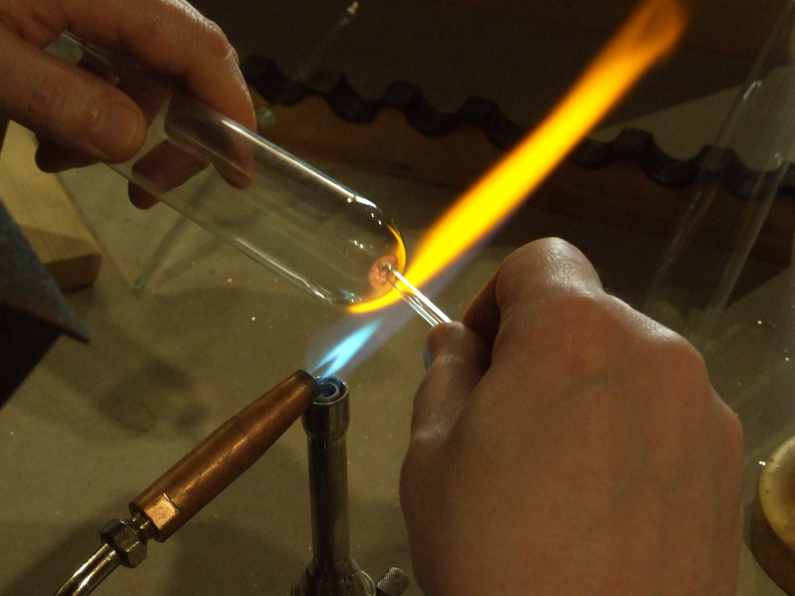
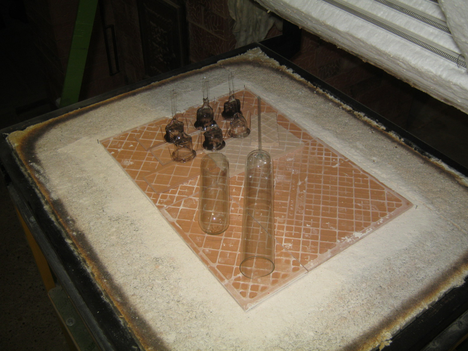
I opened the donor lamps, cut them into convenient pieces about 30 cm long, cleaned the inner walls of phosphor with absorbed mercury, washed the blanks in warm soapy water, and etched them in a 2% hydrofluoric acid solution. All work was performed outdoors — Hg and HF vapors are toxic.
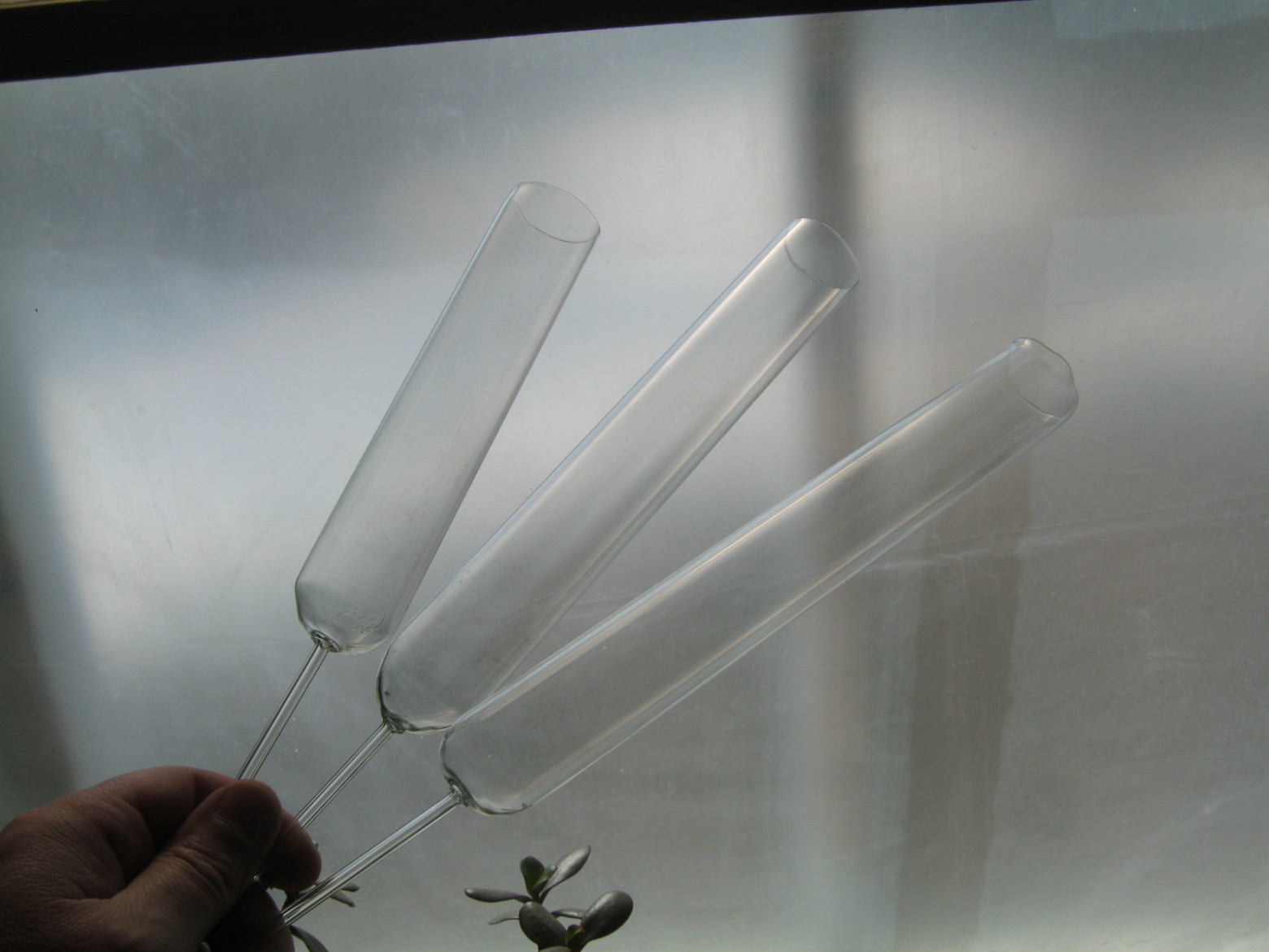
2. Lamp Envelope (Bulb)
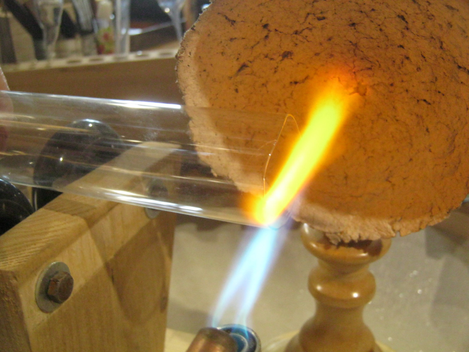
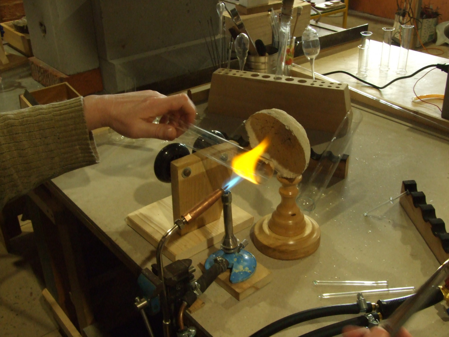
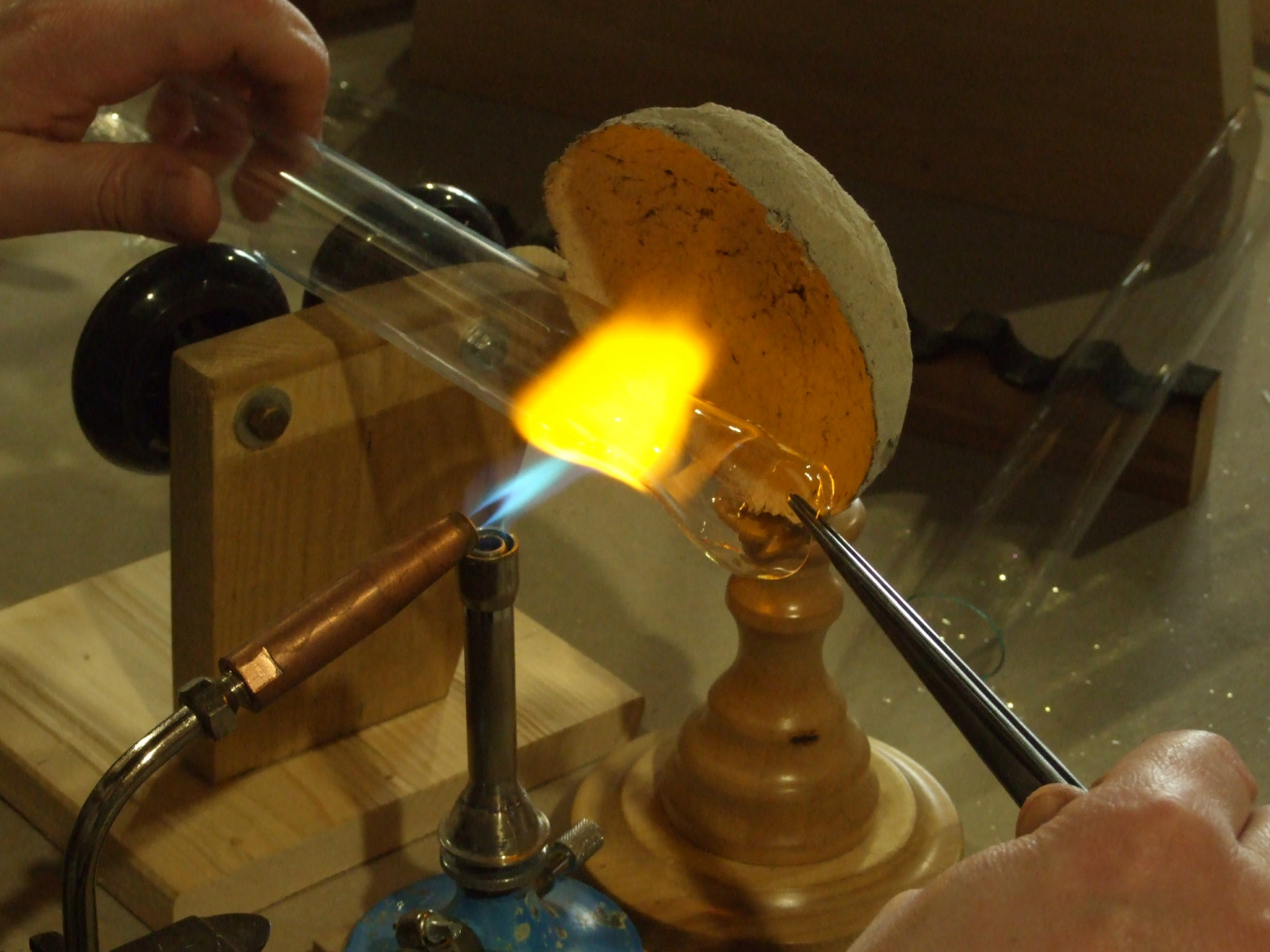
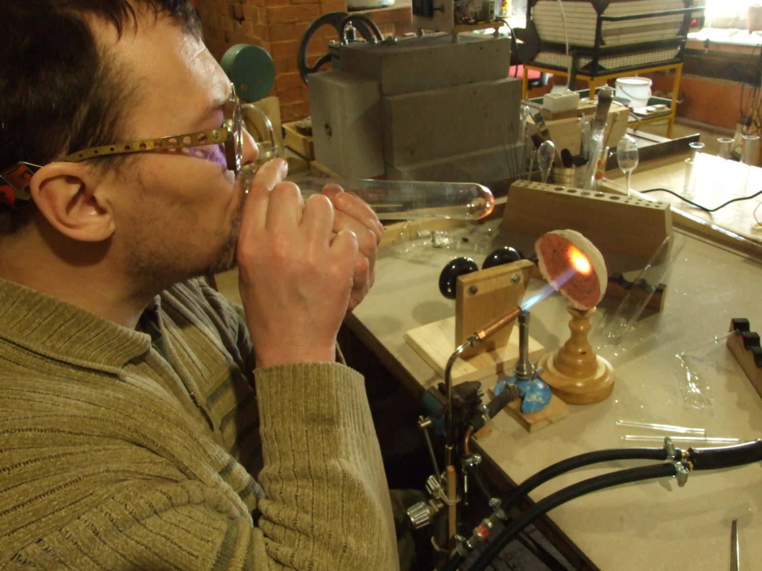
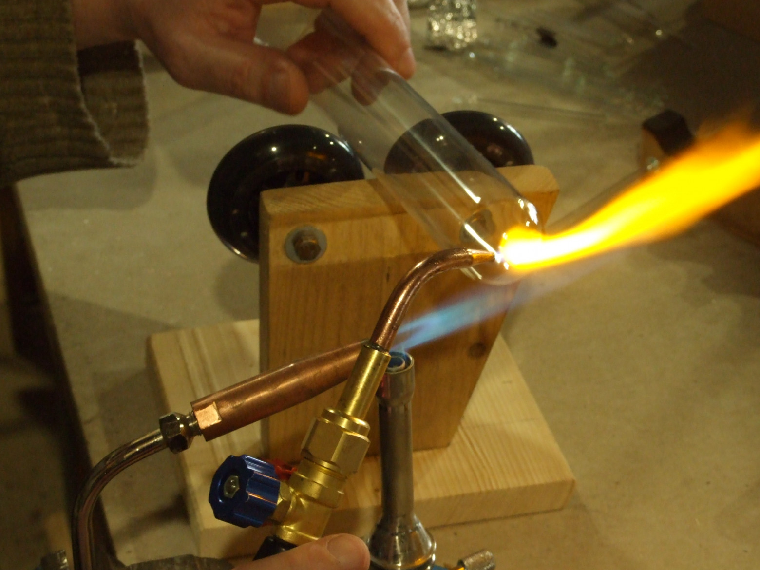
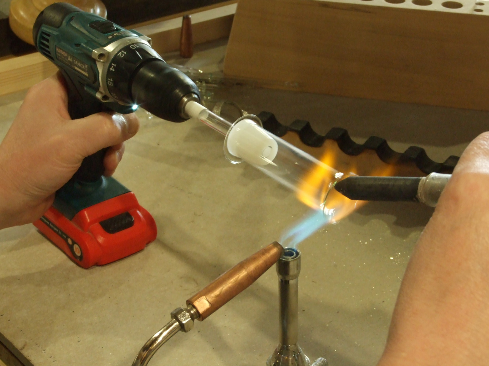
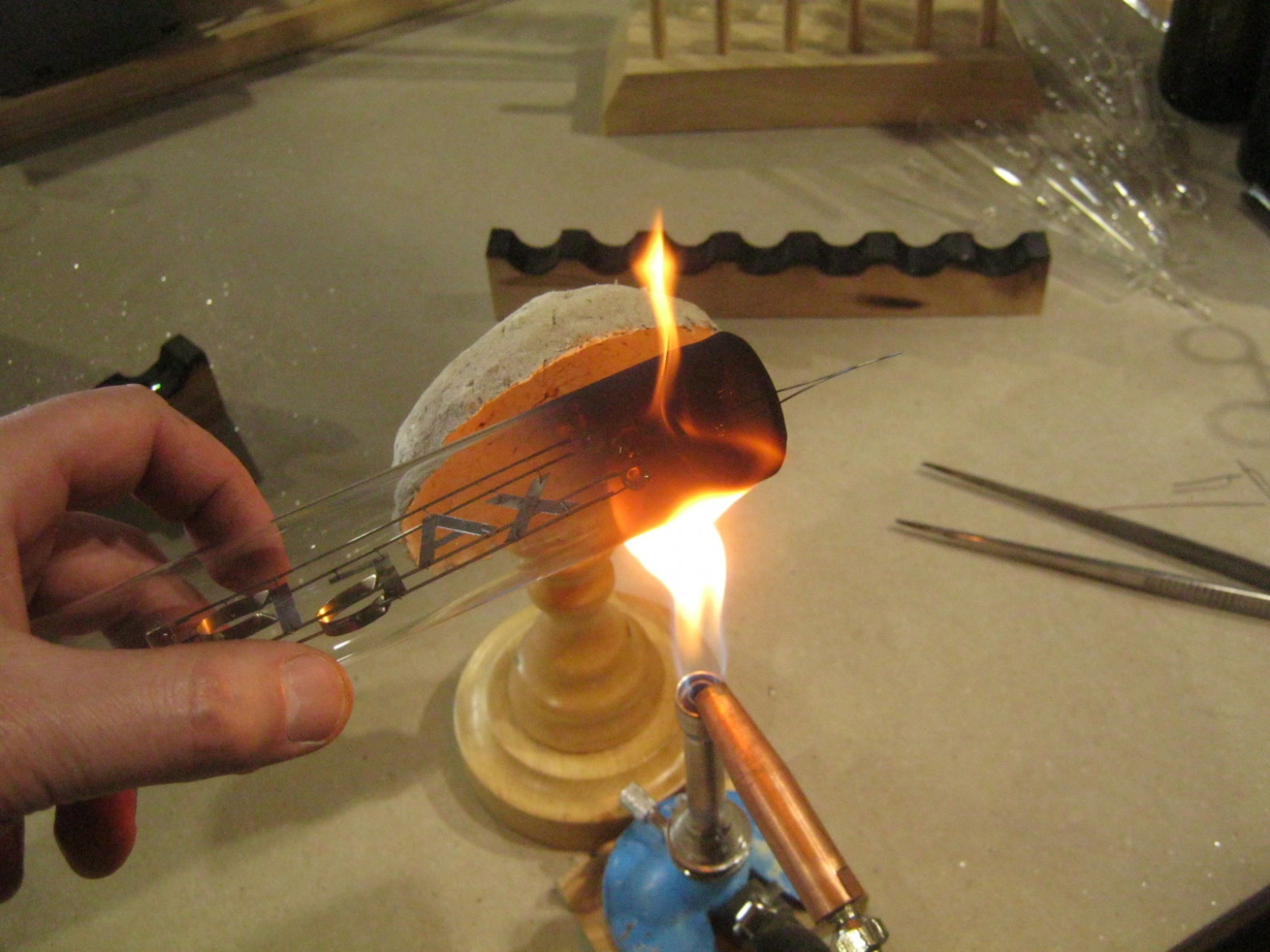
We will make the envelope (bulb) of our lamp straight, cylindrical, with a technological tube — a tubulation (stem) — at the top, which will simplify the fabrication and sealing of the complex assembly: the comb base of the device.
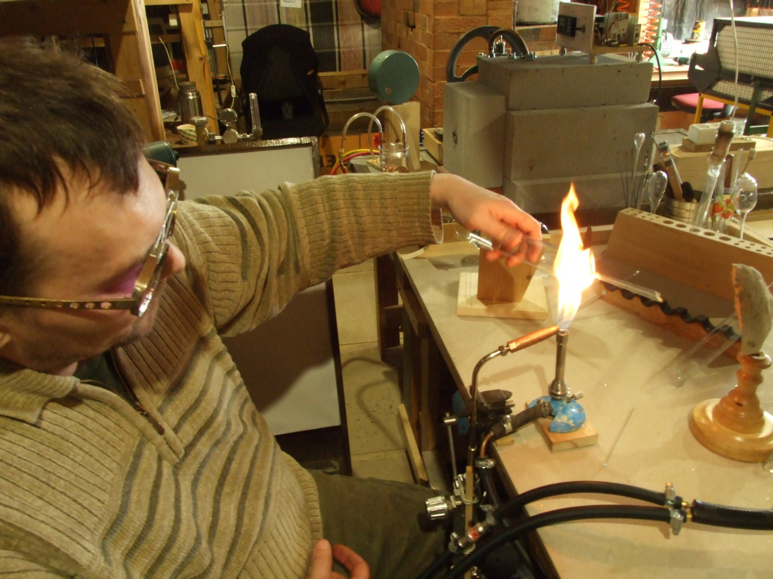
The process involves flame-working the glass tubes: melting and fusing the edges, forming the bottom, creating an opening for the tubulation stem, and final shaping of the cylindrical envelope. Each step requires careful temperature control to avoid cracking the high-CTE platinum glass.
3. Comb Base (Press Stem)
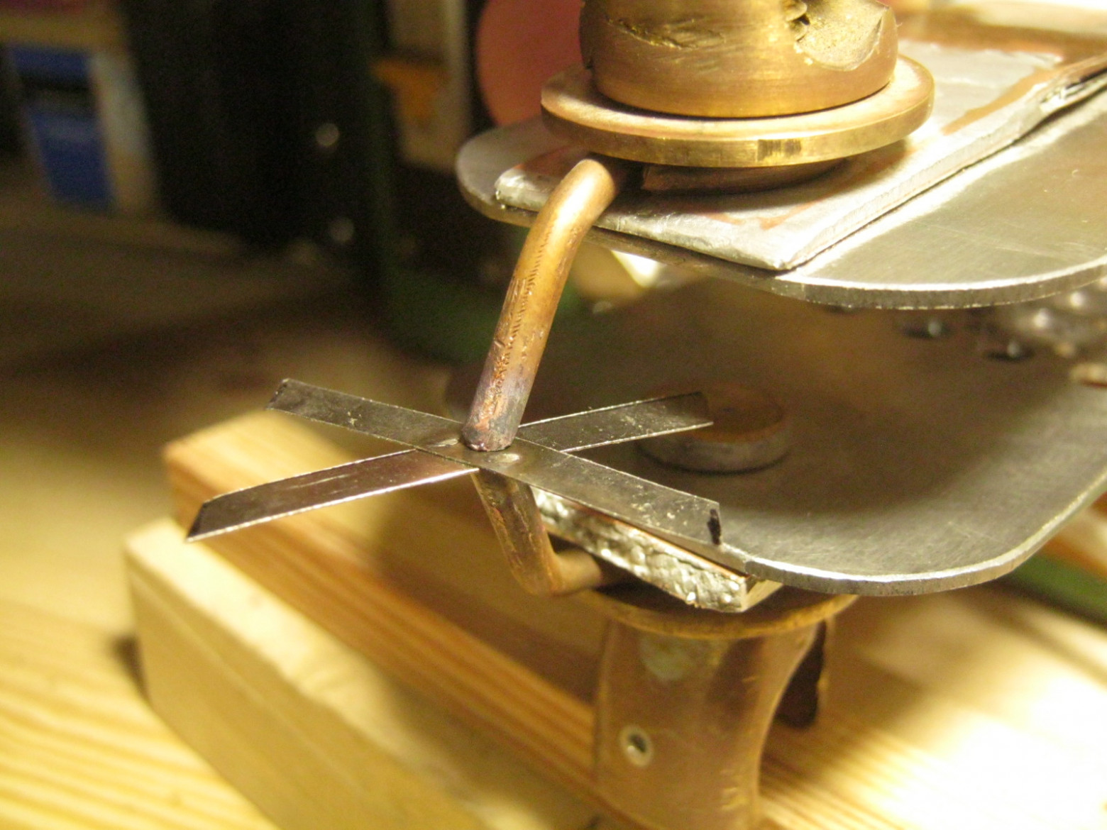
This is a historically early vacuum tube design, simple and well-suited for manual fabrication. The comb base uses three-layer electrical leads: platinite in the center (compatible with glass), nickel on the outer portion (solder-friendly), and stainless steel on the inner portion (resistant to sputtering and corrosion inside the tube).
The leads are assembled using spot welding (contact welding). The base features a flared "skirt" expansion to increase the seal area with the envelope, and a constriction (pinch) where the leads pass through the glass, creating a hermetic seal. The electrodes are mounted to the leads before the base is sealed into the envelope.
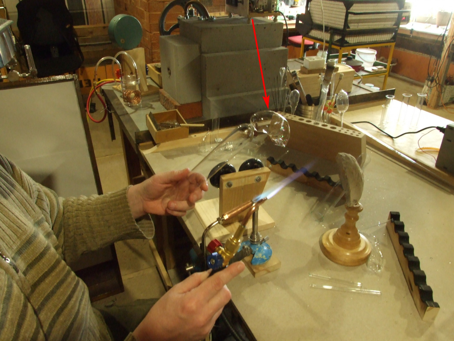
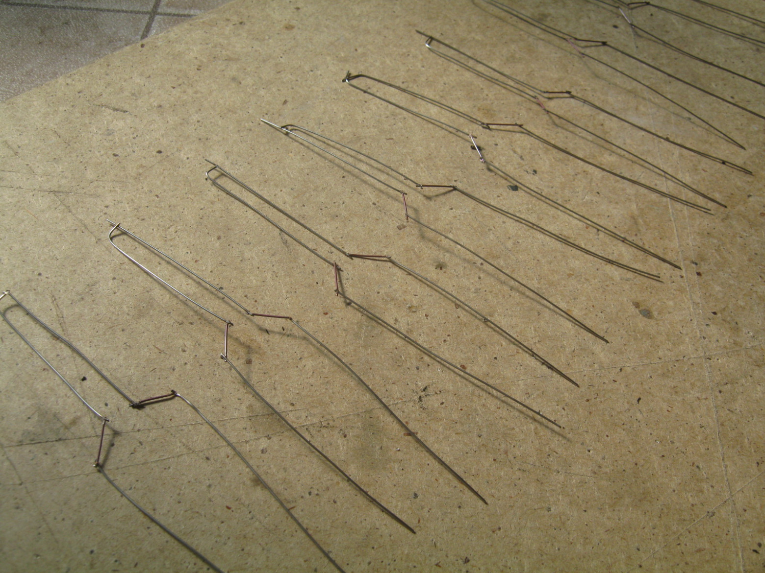
4. Main Electrode System
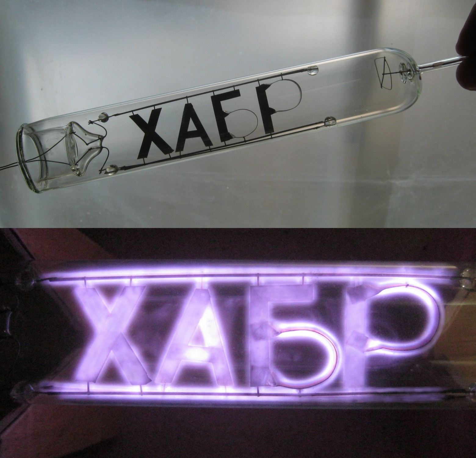
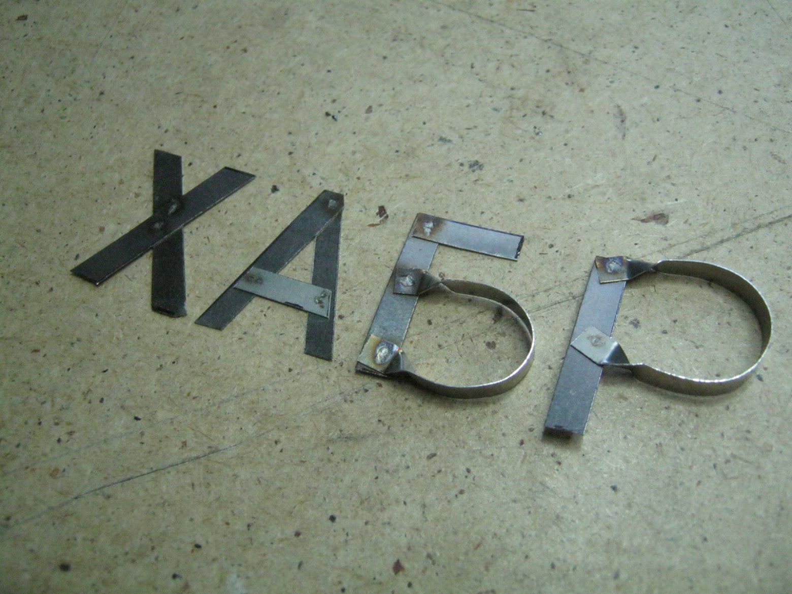
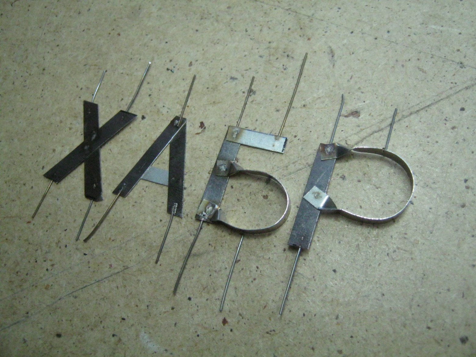
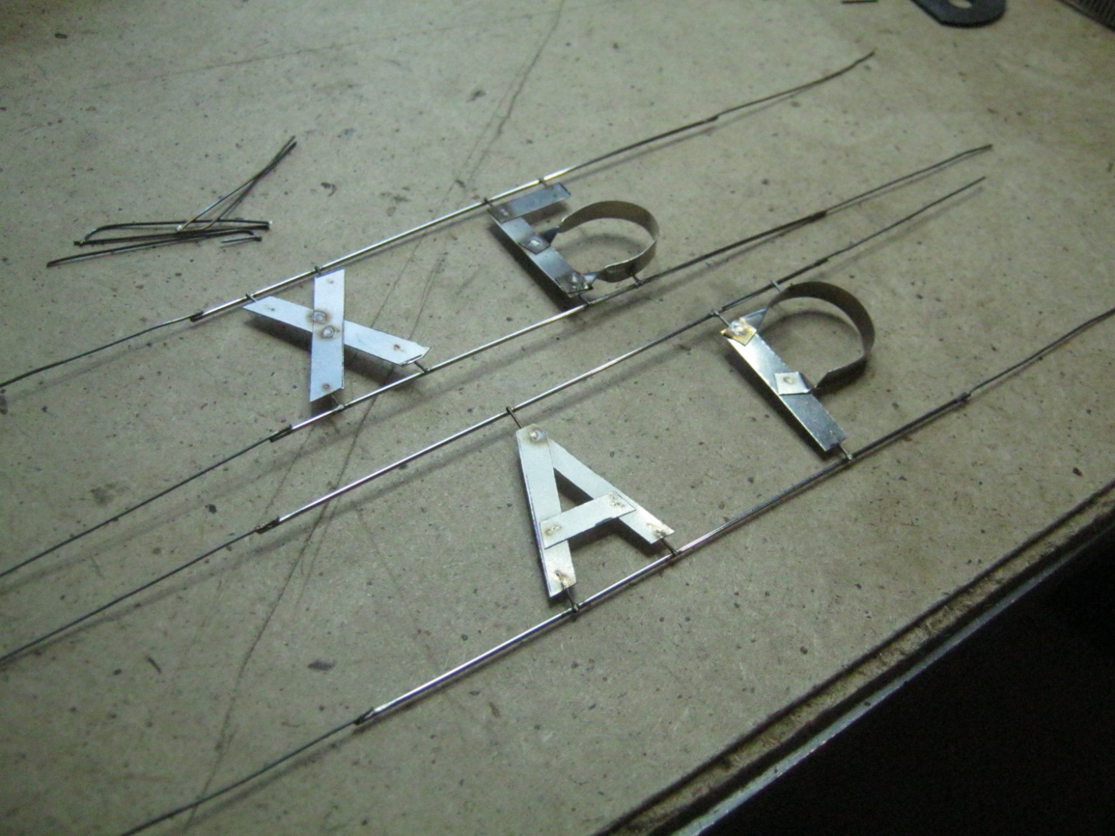
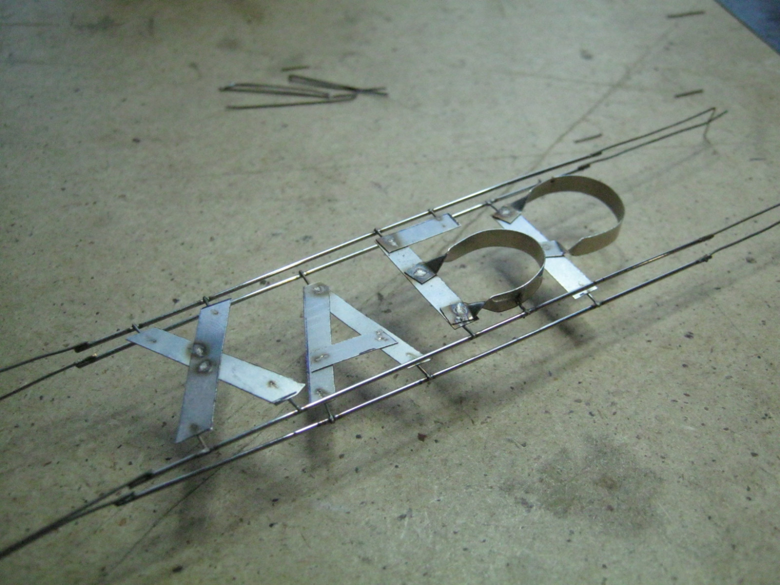
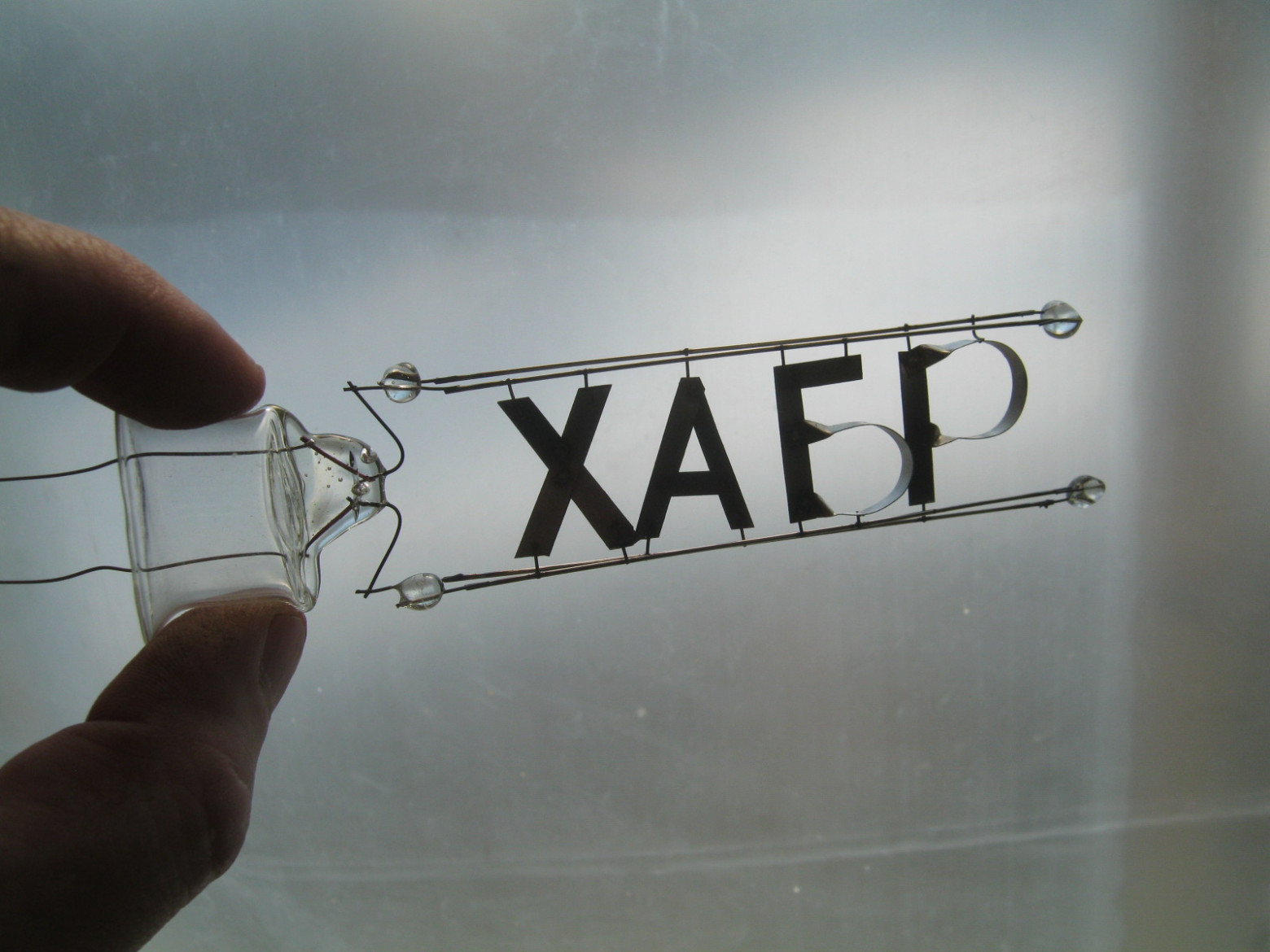
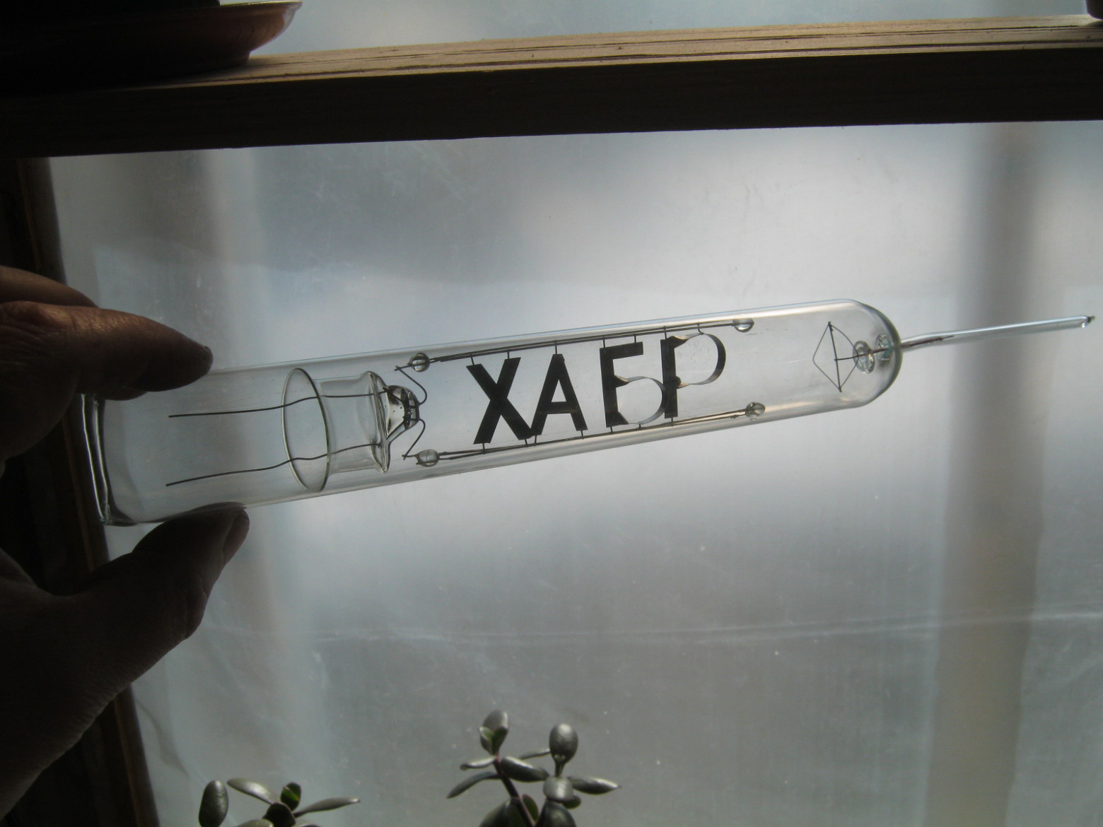
We will make the electrodes in the form of symbols spelling out a short recognizable inscription. Let our lamp operate on alternating current, with both electrodes glowing. We split the inscription into two parts, connecting one to each electrode terminal. The inscription will be "Habr" — the name of the internet community.
"What is that? What kind of cross is that? Tell me, is that a cross? It looks more like the letter 'Khe'. No, dear sir, that is not the letter 'Khe'. It is fate itself." — from the film "An Ordinary Miracle"
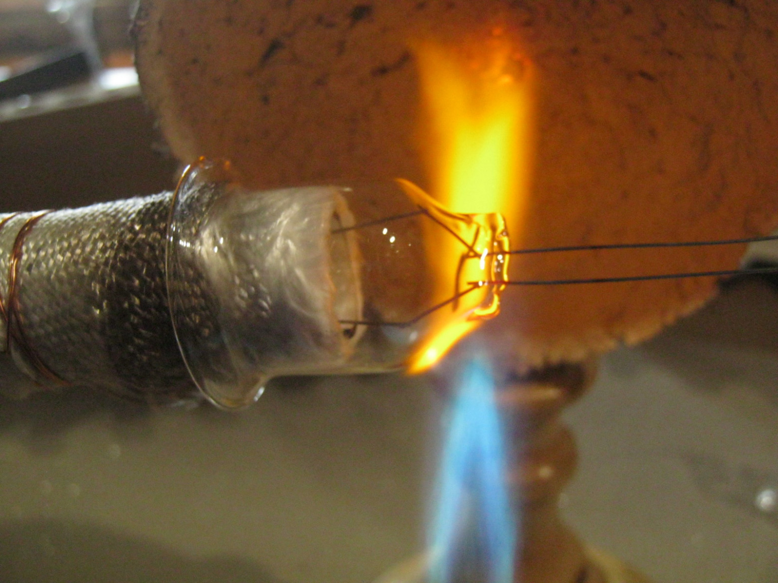
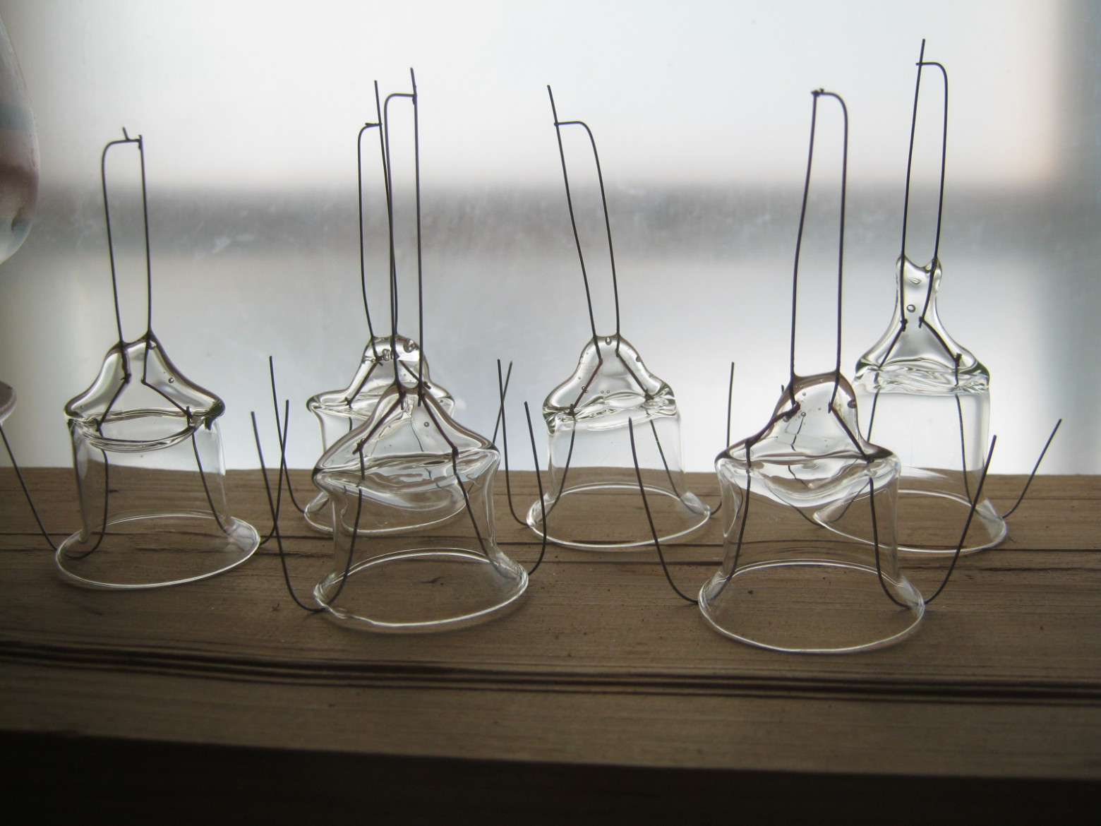
The individual stainless steel letters were cut out and assembled using spot welding. Wire supports hold the letter shapes in position. Two crossbar frames (traverses) hold the electrode groups, with glass insulators preventing short circuits between leads. The gap between the two electrode groups is approximately 3 mm — this is where the gas discharge occurs.
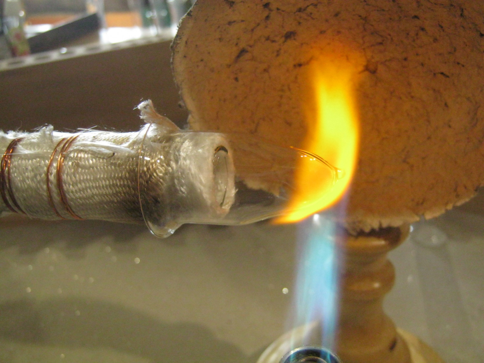
5. Auxiliary Getter Electrode
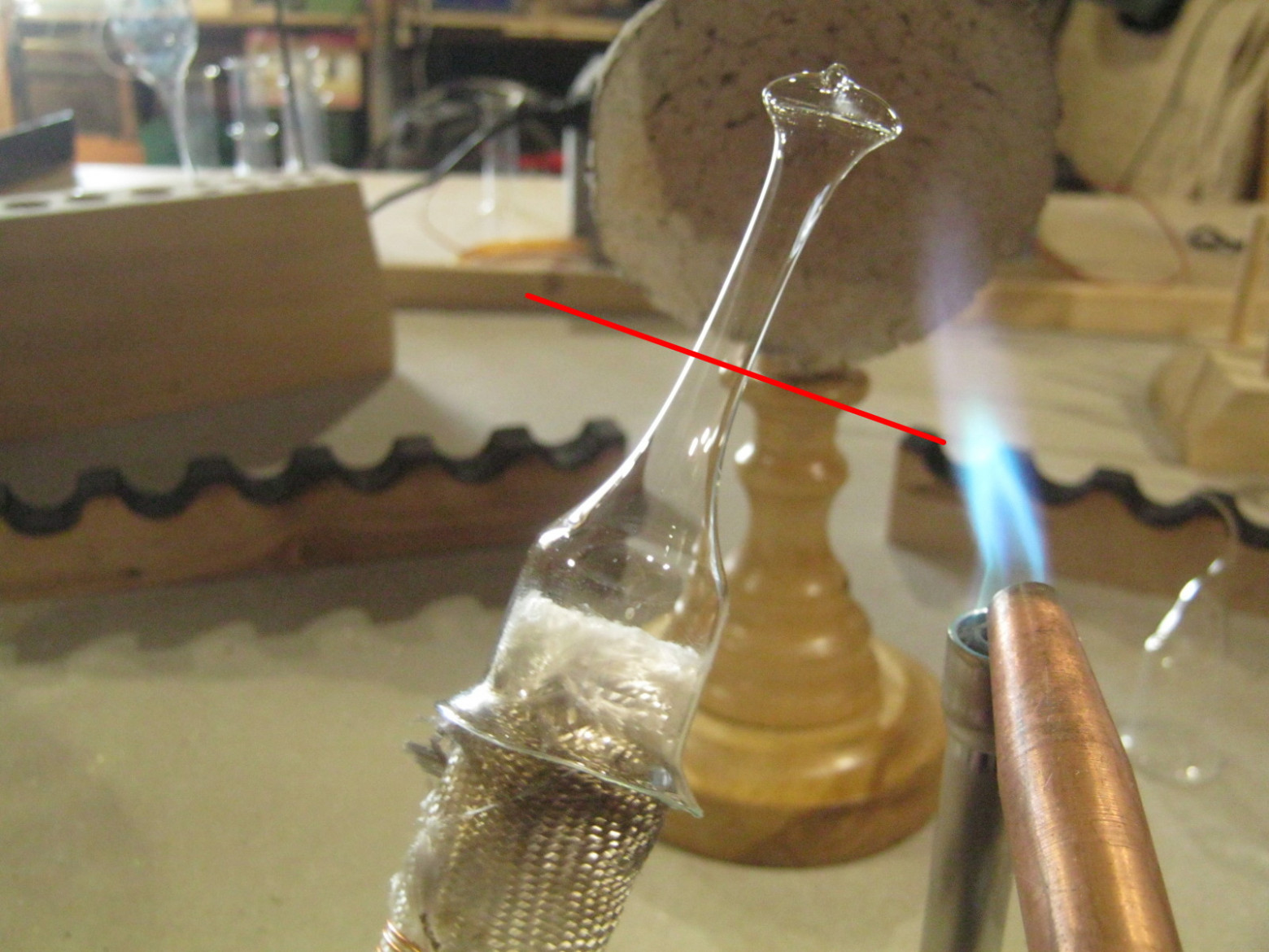
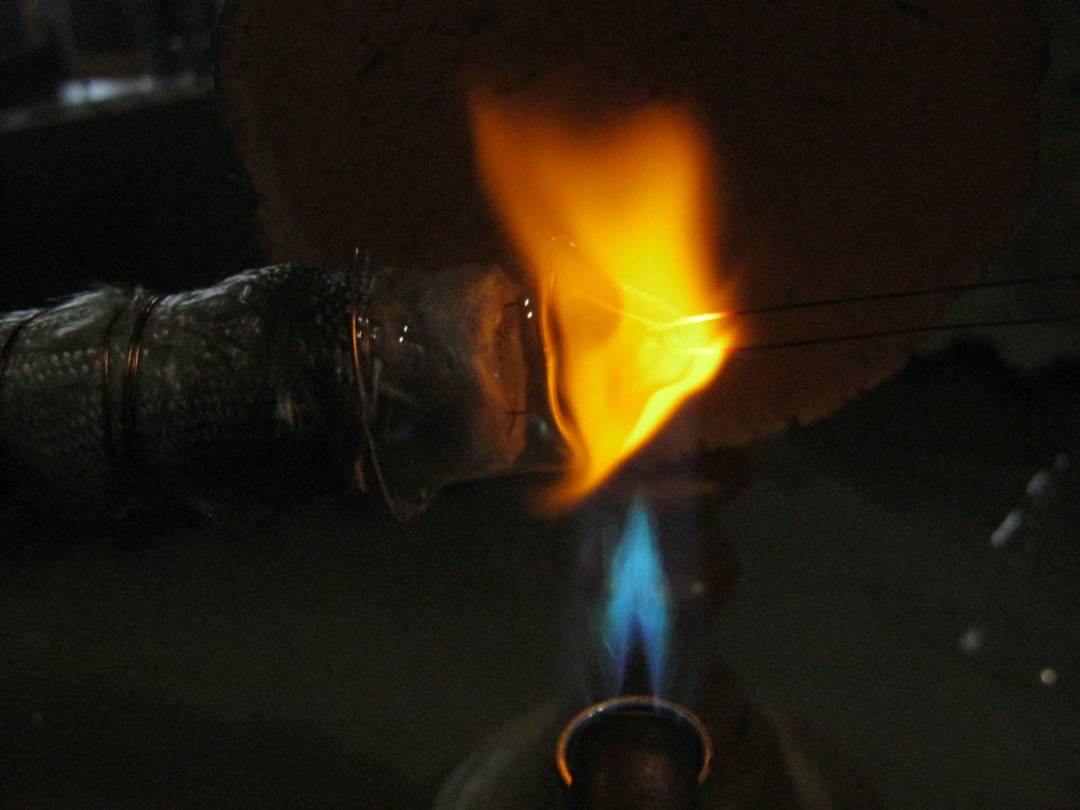
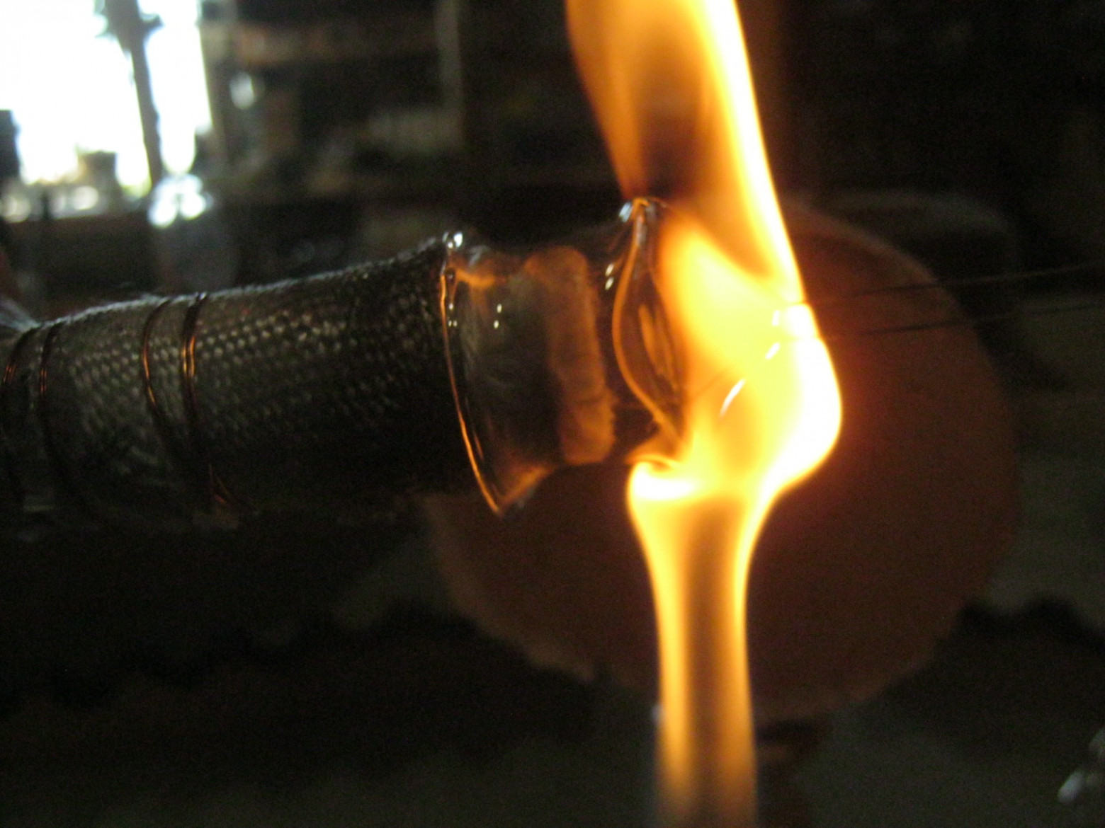
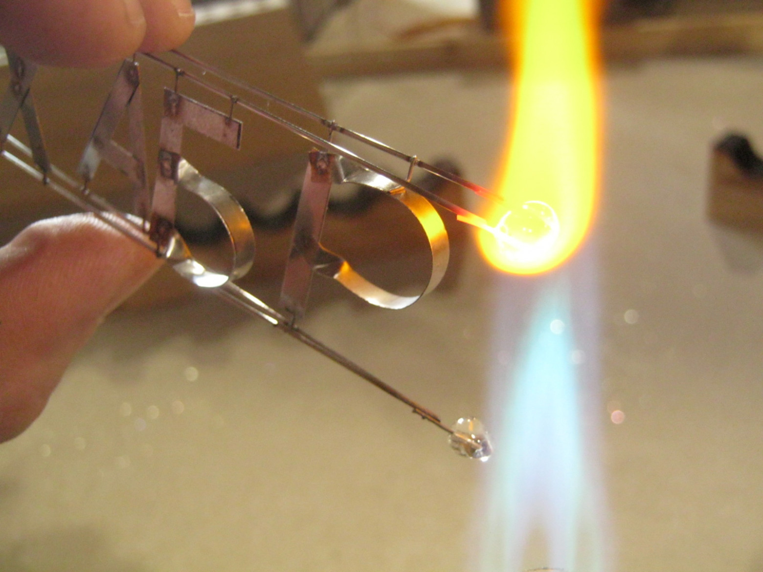
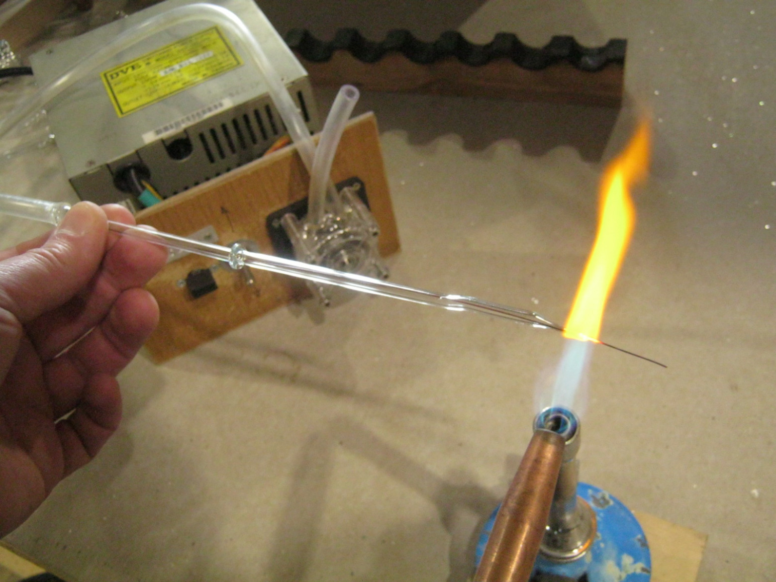
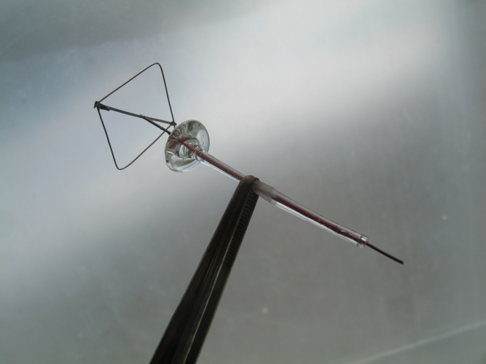
Its purpose is to sputter onto the glass during discharge, binding unwanted gases in the bulb and slightly reducing the pressure of the working gas. The getter metal is titanium. To seal the single getter electrode, we use the tubulation stem already present in the envelope.
The platinite lead of the getter electrode is protected by glass coating (vitrification) — a thin layer of glass melted onto the wire to prevent gas leaks along the metal-glass interface. The getter features a small disc insulator ("saucer") to direct the sputtering appropriately.
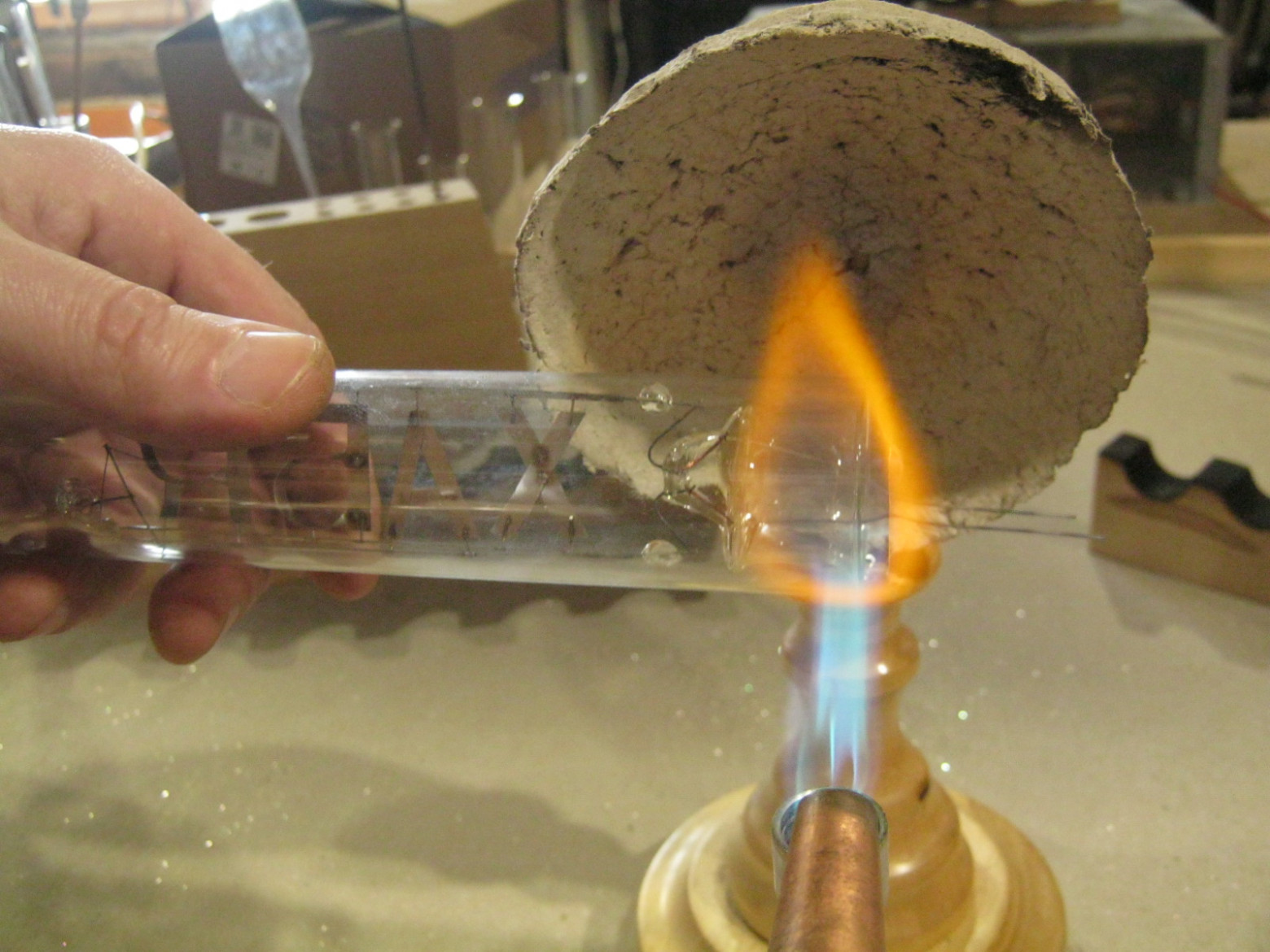
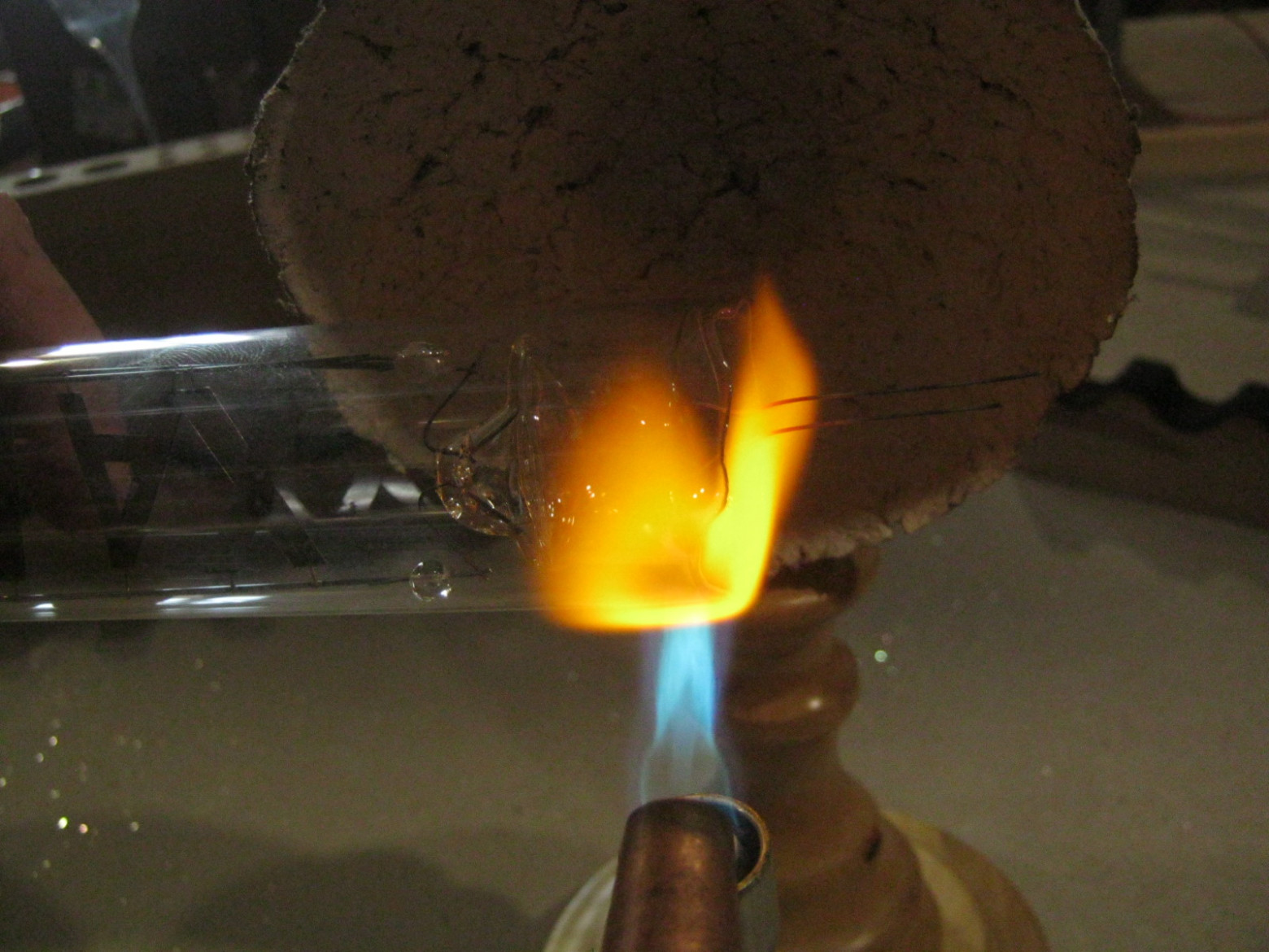
6. Lamp Assembly
The assembly process involves forming the external leads, fitting the electrode system into the envelope, shortening the tube to the proper length, and performing the critical "sealing" operation — fusing the comb base into the envelope using flame-working. The joint must be completely hermetic.
After sealing, the lamp is slowly cooled in a basalt fiber blanket to prevent thermal shock, then annealed in a kiln to relieve internal stresses in the glass. Finally, the atmospheric gases inside are replaced with argon at approximately 200 Pa pressure through the tubulation stem, which is then sealed off.
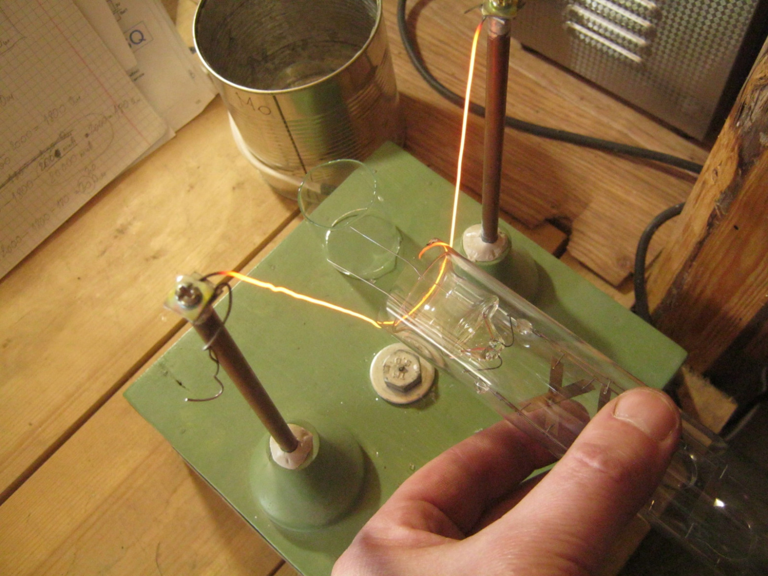
7. Lamp Conditioning: Getter Sputtering
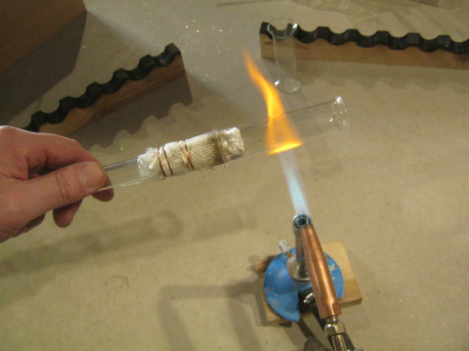
Before the lamp can operate properly, the titanium getter must be activated. This is done through cathodic sputtering — running a DC discharge through the getter electrode for approximately 6 hours at 215 V and about 10 mA. The titanium sputters onto the inner glass walls, forming a thin metallic film that chemically binds residual gases (oxygen, nitrogen, water vapor) and slightly lowers the argon pressure.
8. Powering Up
The final test: the lamp glows on alternating current at 280 volts and a current of approximately 80 mA. The gas discharge illuminates the stainless steel letter electrodes, creating a distinctive glow around the "Habr" inscription.
9. Conclusions
As a result of this work, a quite large electronic vacuum device with a fairly complex electrode system was assembled. The process involved mastering manual tubulation sealing into the top of the envelope, refining complex operations for base fabrication and device sealing, and improving the design of the sputterable getter.
However, despite the lamp's conditional functionality, the electrode design proved unsuccessful — the electrical parameters are poor, and the envelope heats up significantly. The large surface area of the letter-shaped electrodes and the small 3 mm gap mean that too much current flows, causing excessive heating. Future iterations would benefit from thinner electrode material and a larger inter-electrode gap.
10. Additional Materials
- Discharge lamp with titanium getter. Author's notes.
- Groups of vacuum tube glasses. Author's notes.
- Cutting glass tubes. Author's notes.
- Contact welding for small items. Author's notes.
- High-voltage power supply. Author's notes.
- Simplified evacuation and filling of homemade vacuum tubes. Author's notes.
- Amateur vacuum tube maker's library.
For the benefit of all sentient beings, Babay Mazay, April 2025.


