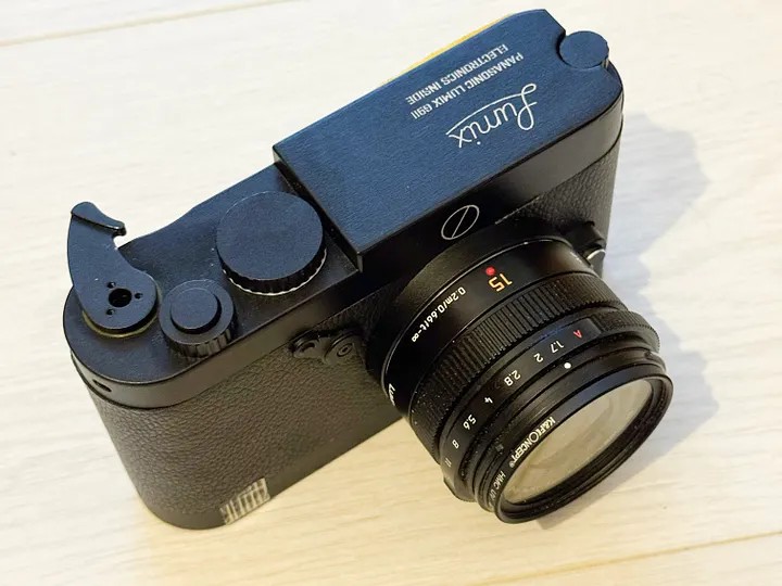
I Dreamed of a Camera That Didn't Exist, So I Built It Myself
A software developer spent over a year transforming a Panasonic Lumix G9ii into a custom Leica M-inspired aluminum-body camera, documenting every step from CAD design to CNC machining and custom flex circuit fabrication.
I've always dreamed of writing custom camera firmware, or at least hiding the menus I never use. But modifying firmware on modern cameras is extremely risky for non-experts — one wrong move and you've bricked a thousand-dollar device. So instead, I went in a different direction entirely: I decided to rebuild the camera hardware from scratch.
Why the G9ii?
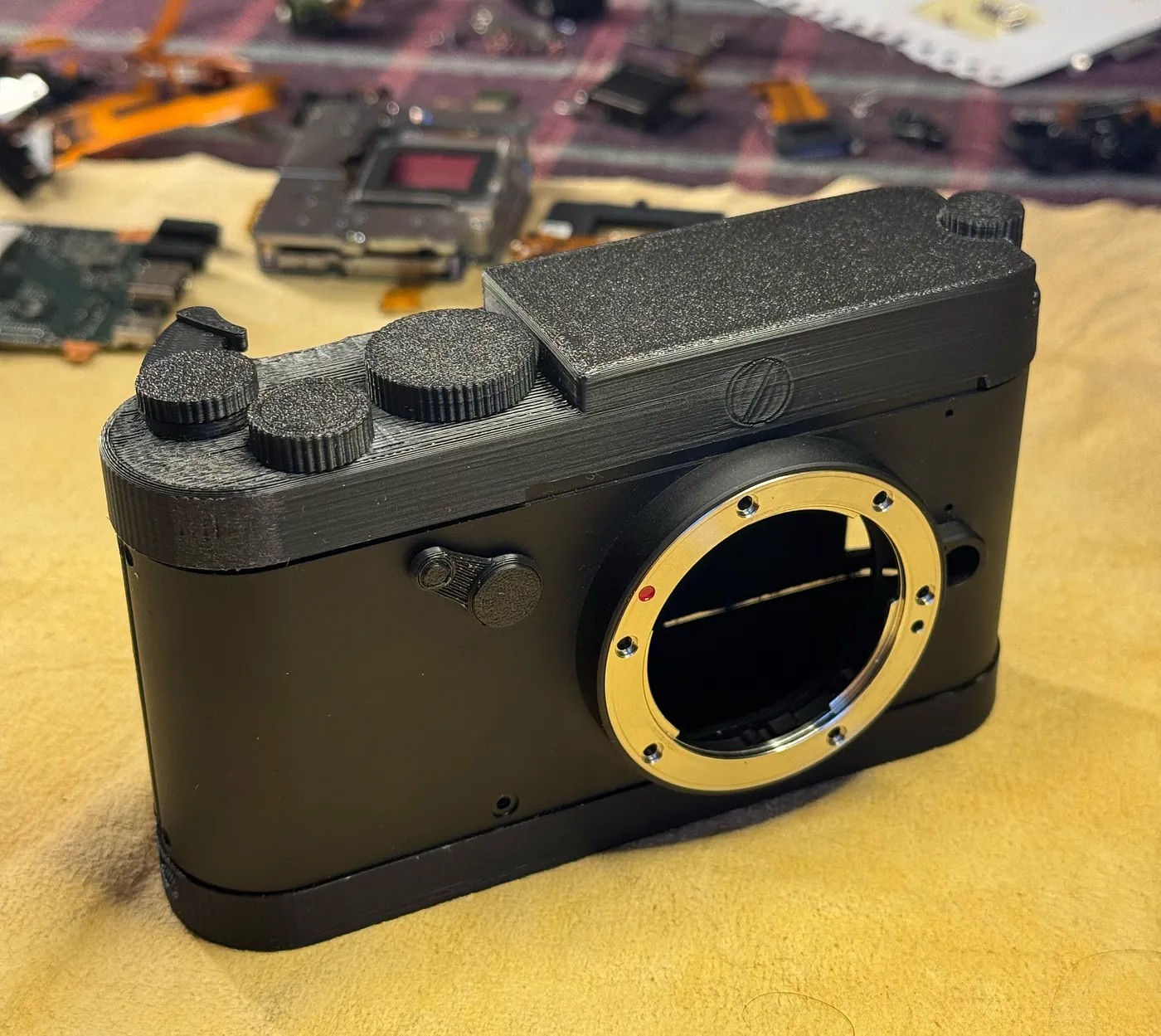
I chose the Panasonic Lumix G9ii because it represents the most functional Micro Four Thirds camera available: highest resolution in its class, phase detection autofocus, dual SD card slots, and excellent video capabilities. My goal was to strip away the unnecessary bulk and create something that felt like a Leica M rangefinder — compact, elegant, and focused on essentials.
Design Requirements
The custom housing needed to meet several criteria:
- Leica M rangefinder aesthetic, inspired by the M70 edition
- Centered lens positioning (avoiding the off-center designs like the Sony a6000)
- Minimal visible fasteners
- Premium materials: aluminum body with leather covering
- Target dimensions matching Leica M proportions: 136 x 80 x 35mm
- Elimination of unnecessary controls and ports
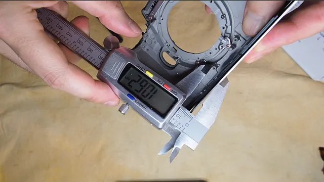
The Measurement Phase
This was the most tedious part of the entire project. Determining the exact positions of original screws, connectors, and PCB mounting points required meticulous calibration using digital calipers against imaginary XY axes. This process consumed several days, and persistent measurement errors meant I had to redo many calculations multiple times.
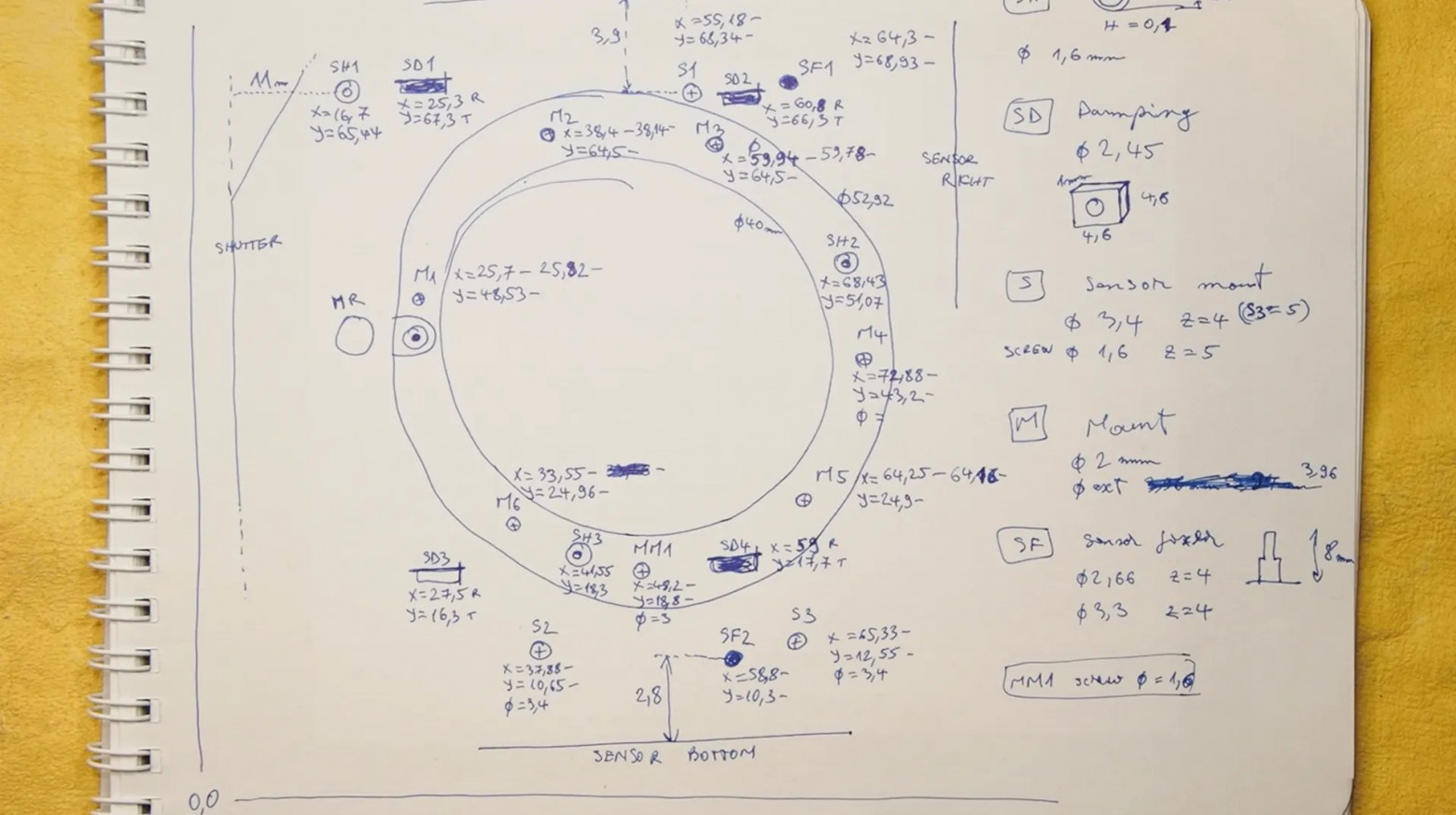
Every millimeter mattered. The original camera's internal layout was never designed to be rearranged, so I had to map every component's exact position and figure out how to fit everything into a significantly smaller enclosure.
CAD Design in Fusion360
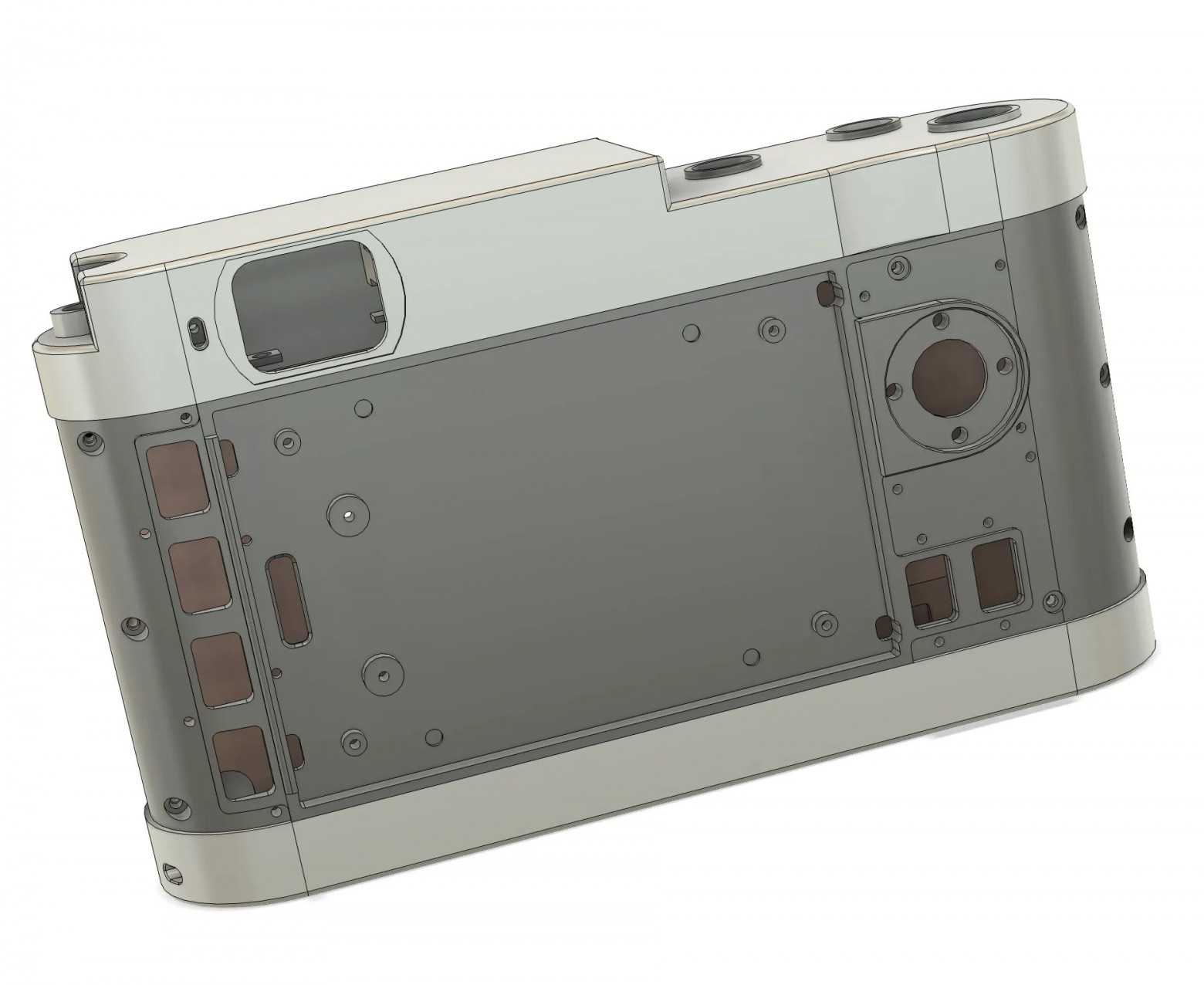
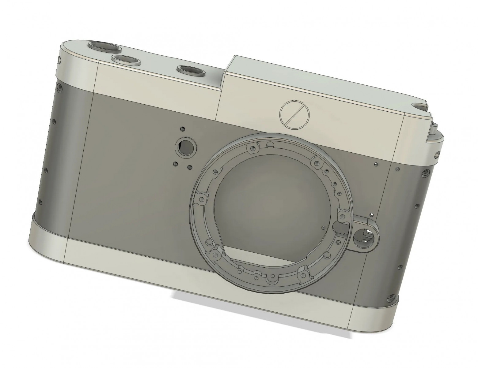
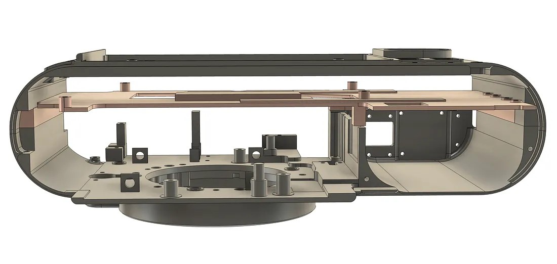
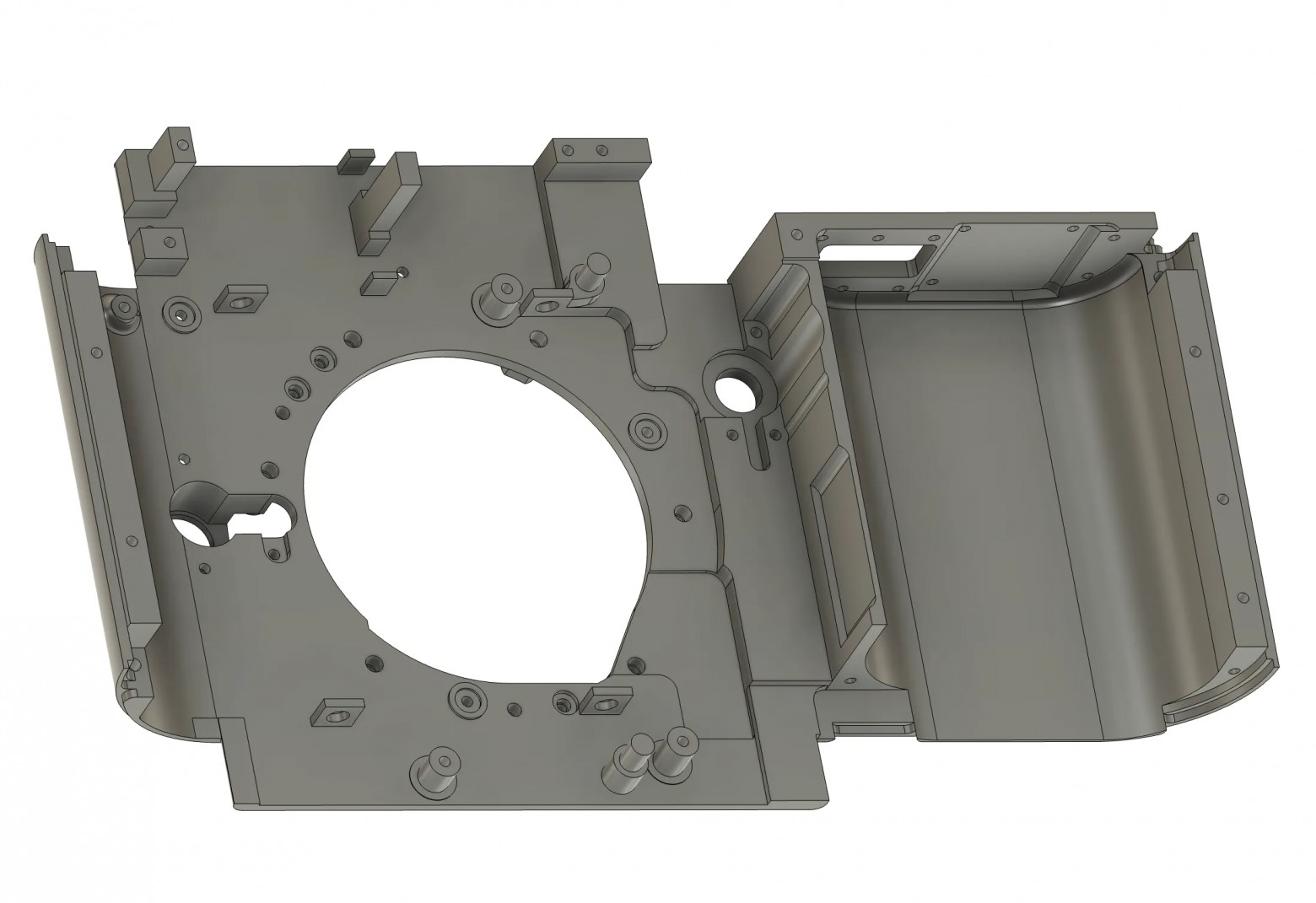
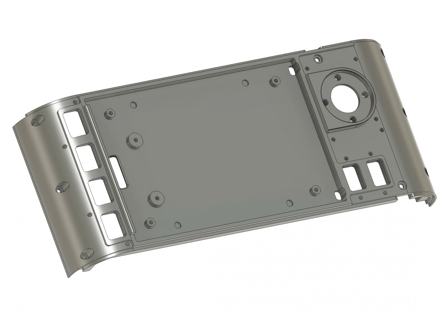
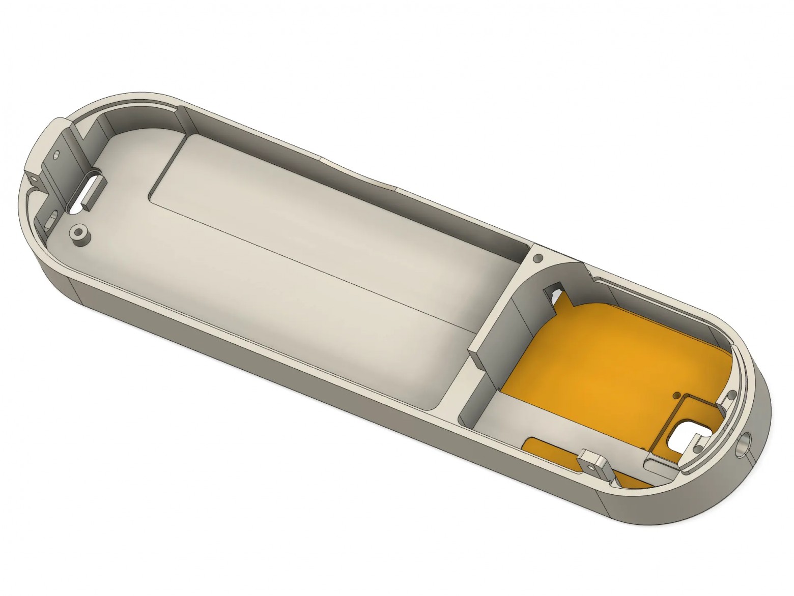
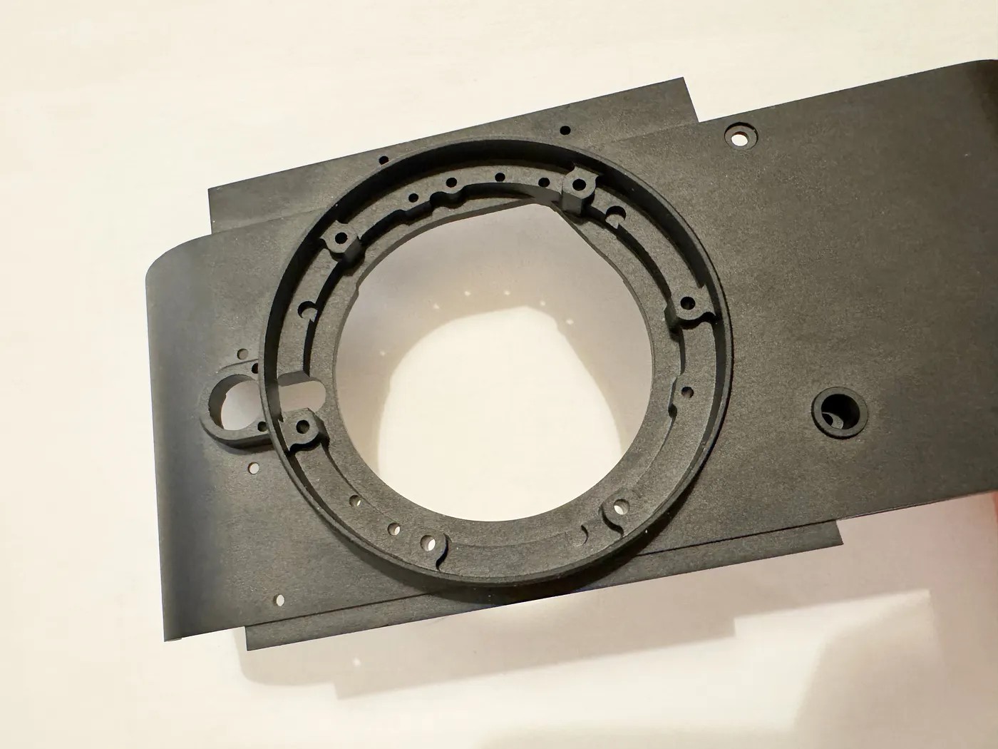
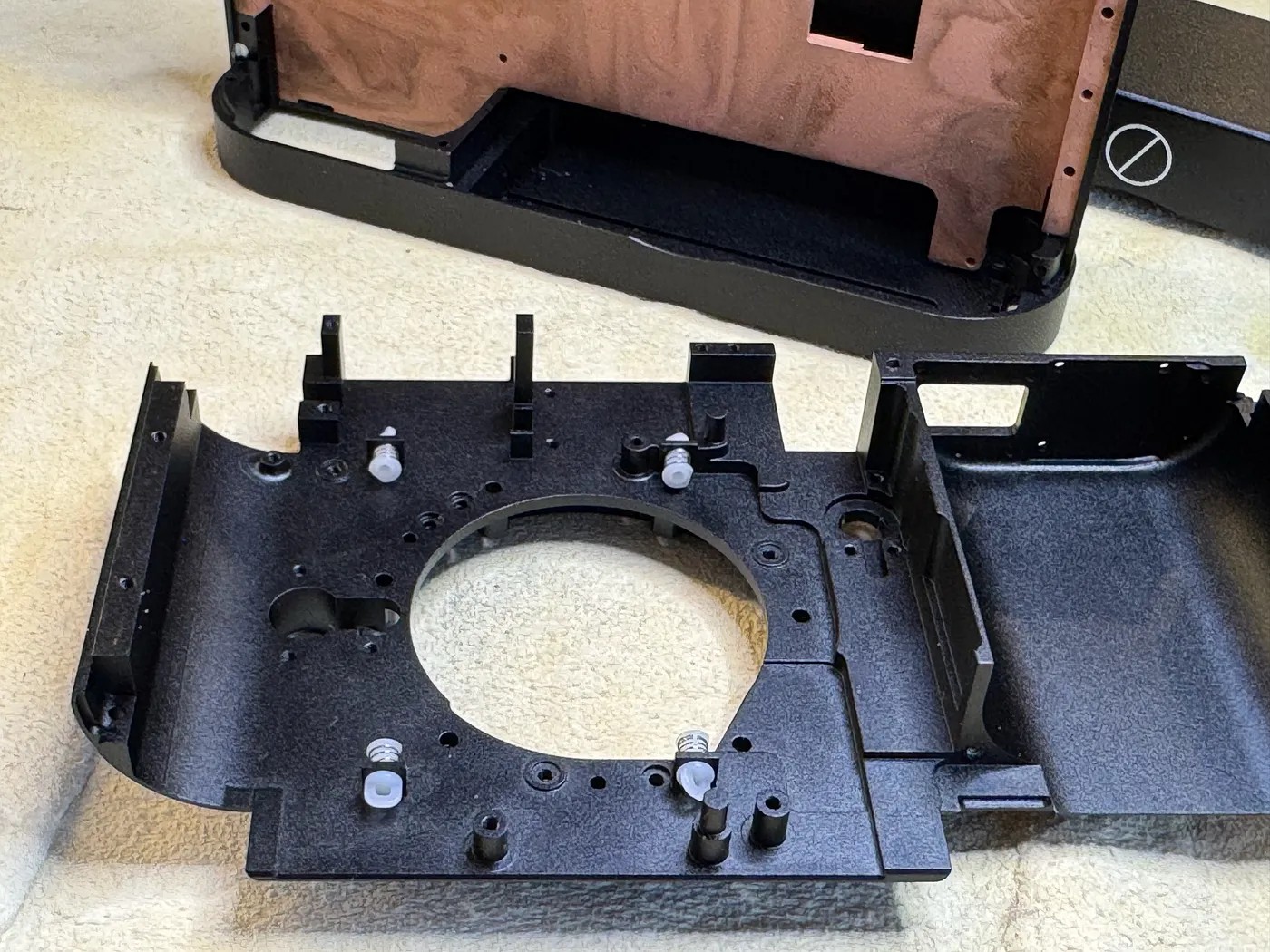
I had zero prior experience with 3D CAD software. Learning Fusion360 while designing a precision camera enclosure was like learning to swim by jumping into the ocean. The housing consists of four main aluminum parts: top plate, bottom plate, front section, and back section. The parts use stepped edges for water and dust protection.
I went through multiple iterations, 3D printing test versions before committing to CNC aluminum. The 3D prints helped catch issues that weren't visible in the CAD model — clearance problems, ergonomic issues, and assembly sequence conflicts.
CNC Manufacturing
JLCPCB produced the CNC-machined aluminum parts. The machining quality was excellent for the price. Hard anodizing provided superior durability compared to standard anodizing — the surface feels premium and resists scratches remarkably well.
The final aluminum housing weighs 234g with the heat spreader — only 46g more than the original magnesium body, despite including a copper thermal interface layer.
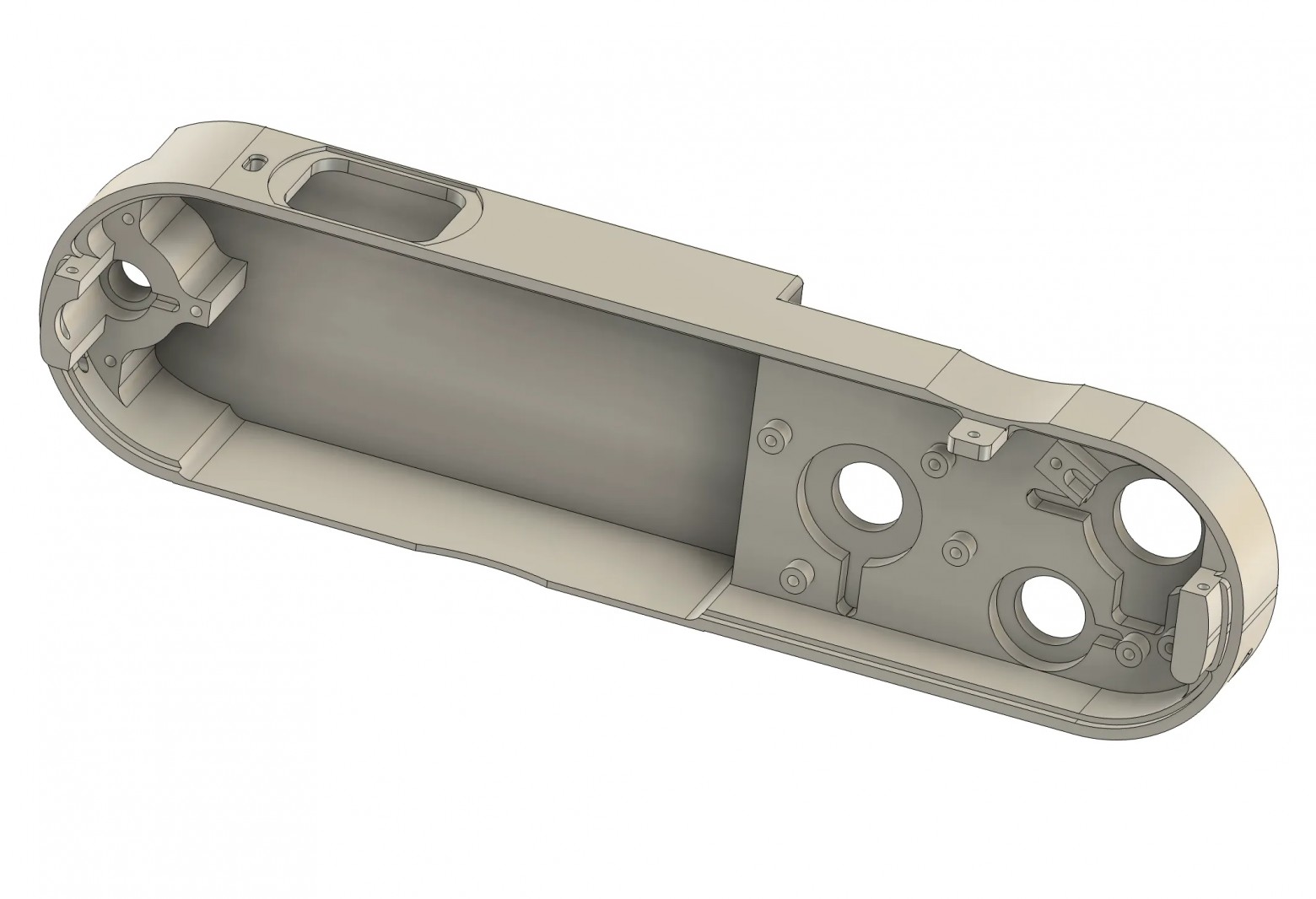
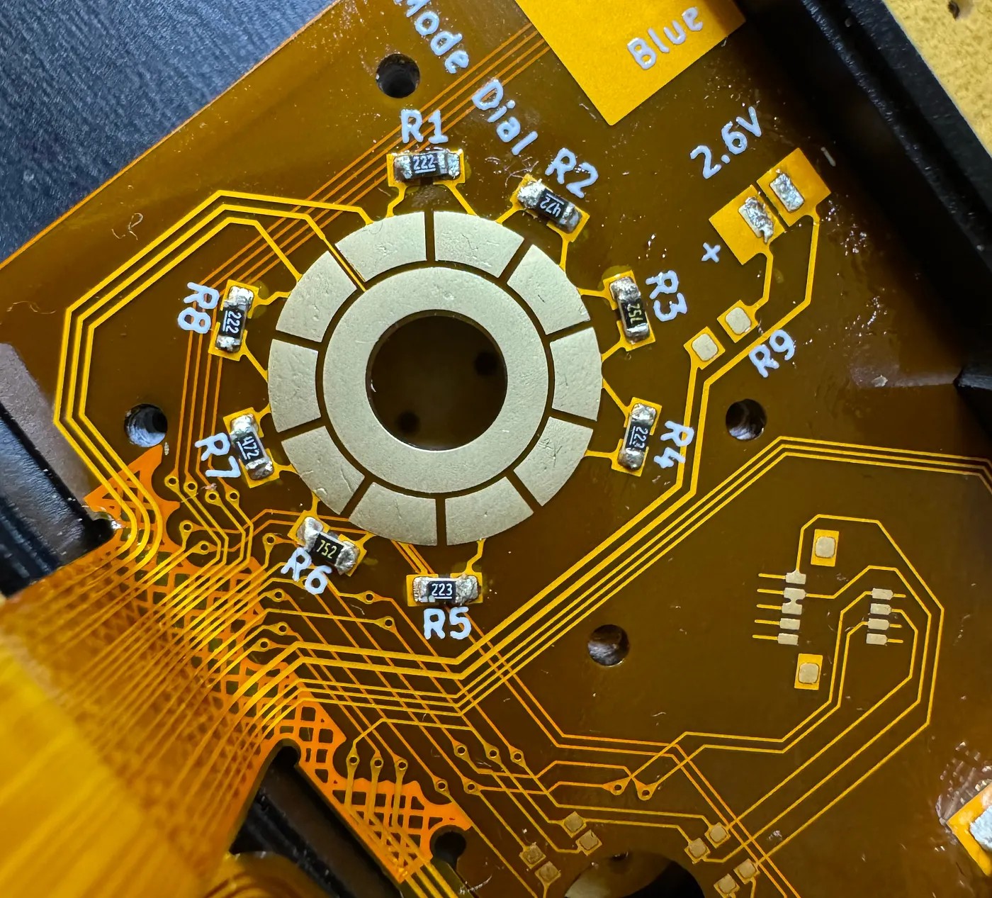
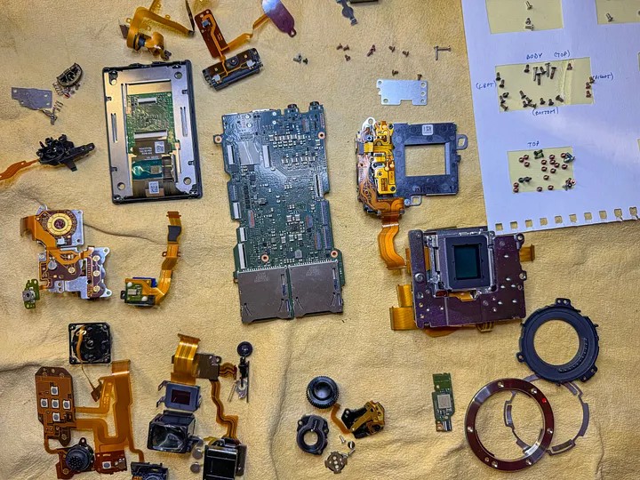
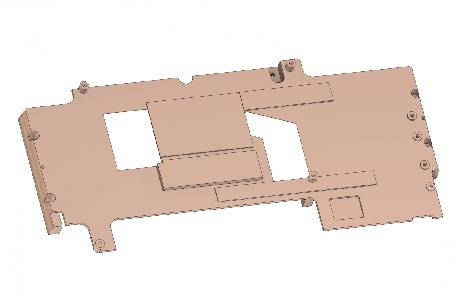
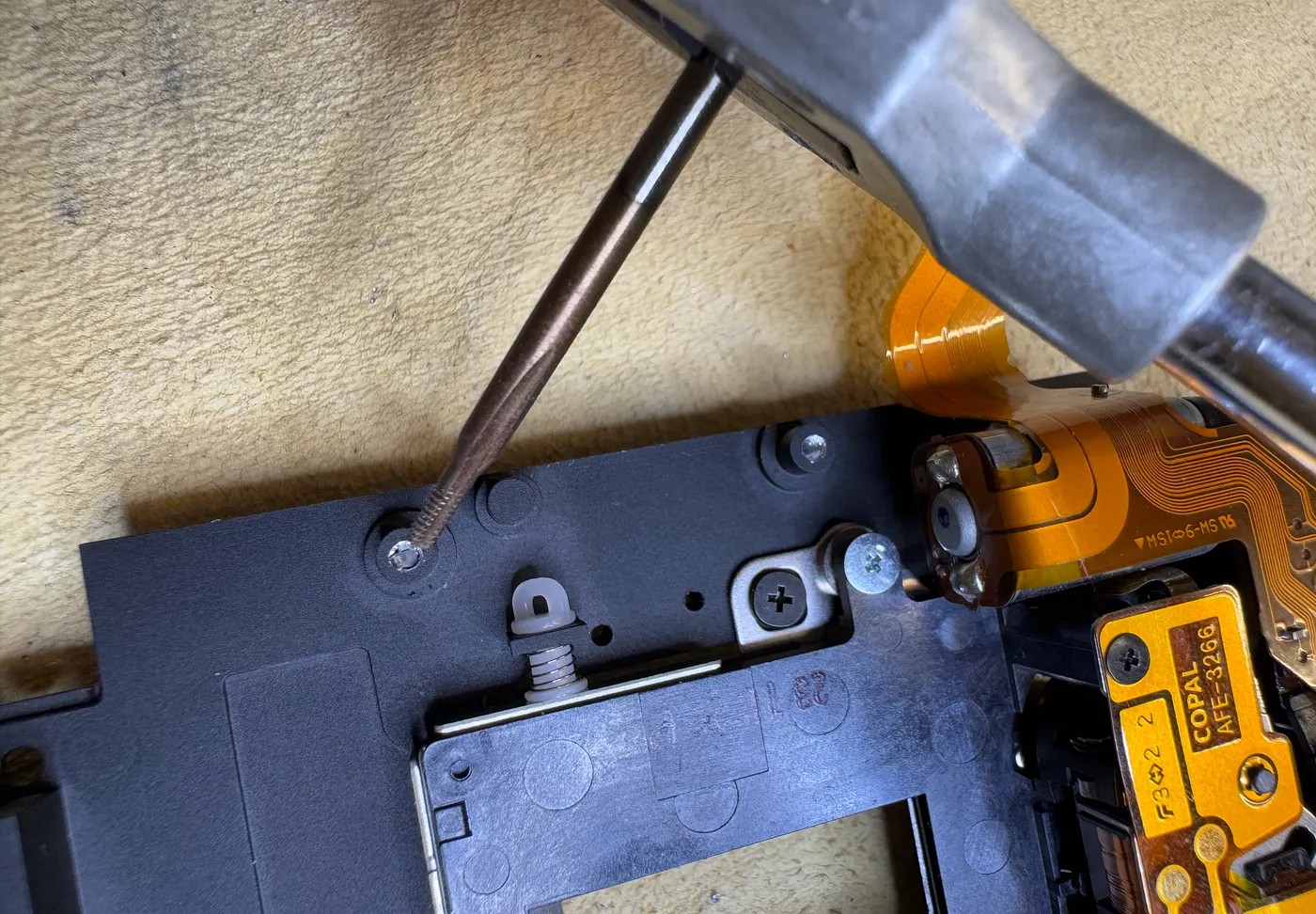
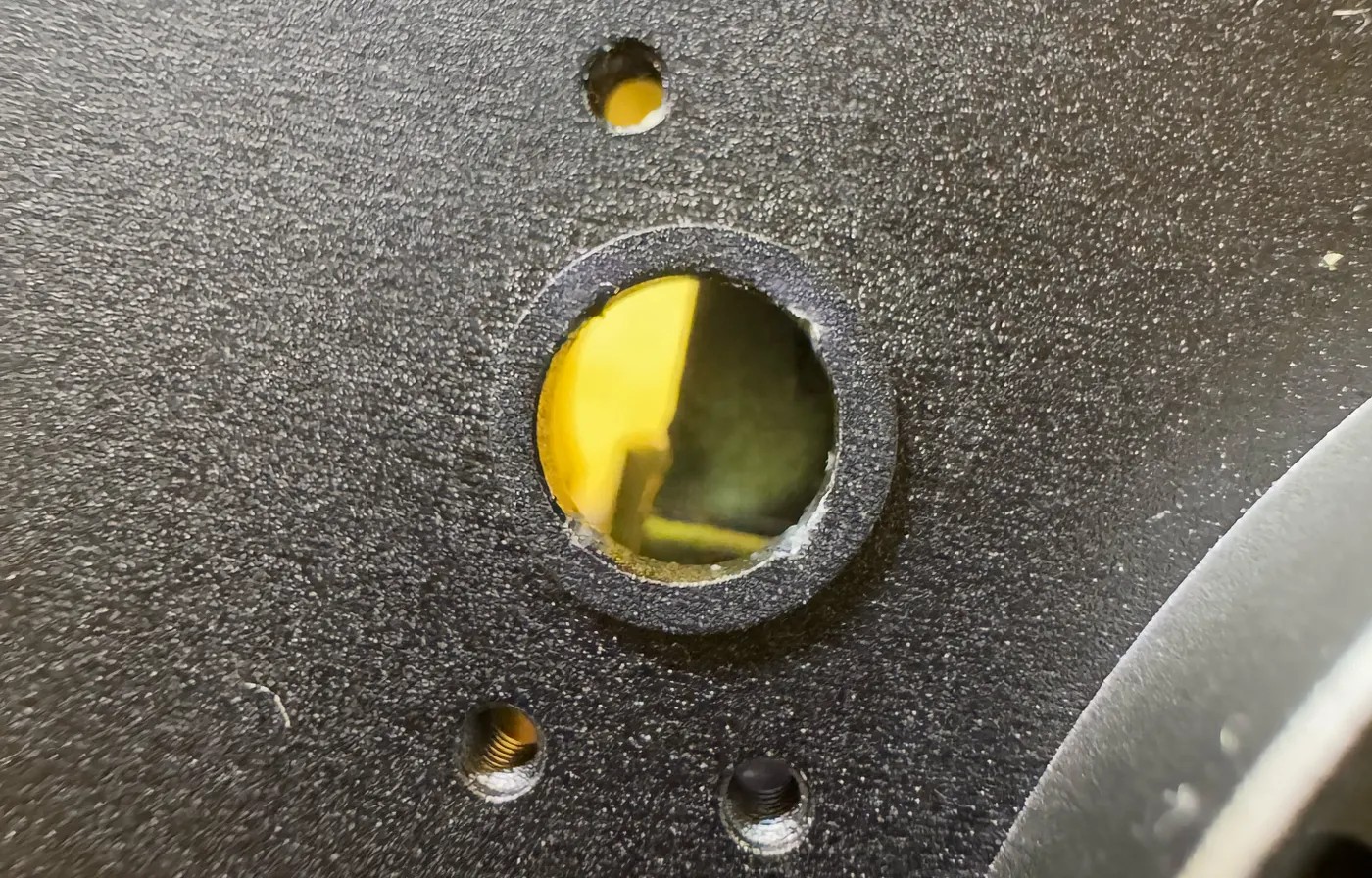
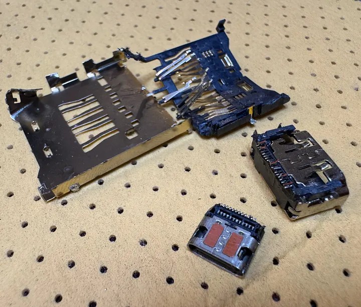
The PCB Surgery
This is where things got really scary. The original camera PCB has eight internal copper layers. When I started cutting the board to remove unnecessary connectors and reposition components, I had to be extremely careful not to damage ground planes or signal traces.
Removing connectors seemed straightforward until I discovered unexpected side effects. After removing the microphone connector, the camera started permanently displaying microphone level indicators on screen. The fix required bridging specific pads to trick the firmware into thinking the microphone was still connected.
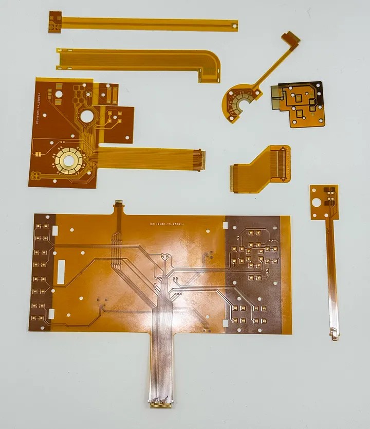
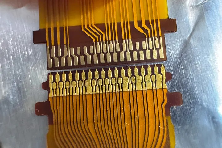
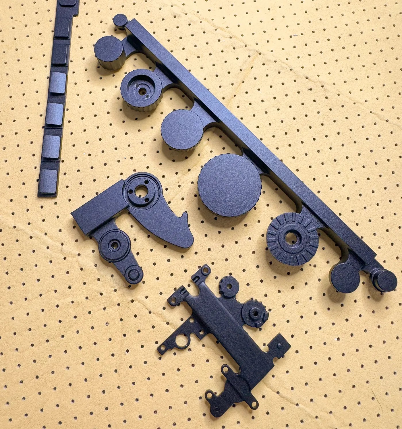
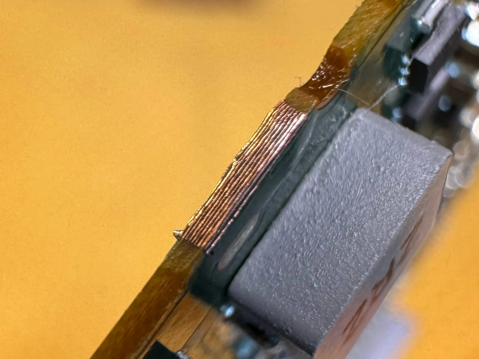
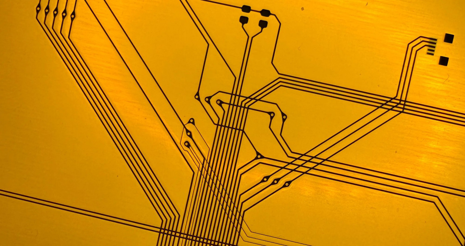
Custom Flexible Printed Circuits
This was the most challenging part of the project. The original camera uses flat flexible cables (FPC) to connect the main board to buttons, dials, and the screen. My redesigned layout required completely new flex circuits.
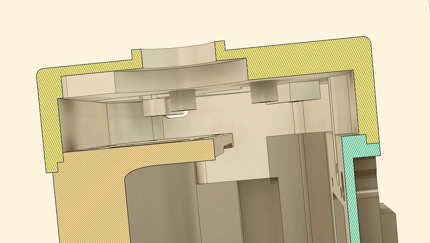
The connectors use 61 pins with 0.4mm pitch spacing. Designing circuits at this scale in KiCad was an exercise in patience. I upgraded component sizes from 0402 to 0603 for better reliability during hand soldering. Some modifications — including the electronic viewfinder connection and USB-C repositioning — had to be abandoned because routing the flex circuits proved impossible within the space constraints.
Assembly
Putting everything together was nerve-wracking. The SD card slot had to be rotated 90 degrees. The battery orientation was reversed. Every component had to fit within tolerances measured in fractions of a millimeter.
Cost Breakdown
- Used G9ii camera body: €1,000
- Replacement battery: $38
- Tools (calipers, soldering equipment, etc.): $315
- Electronic components: $127
- CNC machining at JLCPCB: $870
- 3D printing prototypes: $6
- Custom flexible PCBs: $148
Total: approximately $2,504 — less than the cost of a new Leica M body.
Known Issues
The project isn't perfect. Several problems remain:
- Control wheels rotate too easily and inconsistently; only the mode dial works reliably
- Sensor calibration data was lost during disassembly (fortunately, no visible artifacts in photos)
- WiFi signal is severely attenuated by the all-aluminum chassis
- Housing reaches 35-40°C during extended use due to heat buildup
- Battery depletes faster than the original design due to thermal management changes
Sample Photos
Despite all the modifications, the camera produces excellent images. The sensor and lens mount remain unchanged, so image quality is identical to a stock G9ii. The main difference is how it feels in your hands — smaller, lighter, and undeniably more beautiful.
Conclusion
This project took over a year and required learning CAD design, CNC manufacturing, flex circuit design, and precision electronics work — all from scratch. The result is a one-of-a-kind camera that combines modern Panasonic imaging technology with the aesthetic of a classic Leica rangefinder. All design files are published on GitHub, and the build process is documented on my YouTube channel "Camera Surgery."