Grip Force Meter: When I Seriously Overestimated My Strength
A DIY electronics project building a hand dynamometer from a Nokia display, ATmega328P, and a 200kg load cell — only to discover the author's grip maxes out at a humbling 49 kilograms.
Greetings, !
I recently recalled my school years and how we spent our free time. Many of us played sports. During PE classes, the teacher often organized various competitions (not like nowadays, where kids go skiing once per winter and spend the rest of the time in the gym). Usually it was running, pull-ups, long jumps, etc. (specifically in a competitive format), but everything changed when arm wrestling competitions were organized, and even between different classes. After that, during breaks we'd look for a free table to continue the competitions — it was incredibly fun. Those who went to the gym started intensively training their forearms and shoulders. Almost everyone had a hand gripper. No, I didn't attend a sports school — I was in a physics and math program. We just didn't have phones and tablets. More than 20 years have passed since then, but I still love sports, as much as time allows.
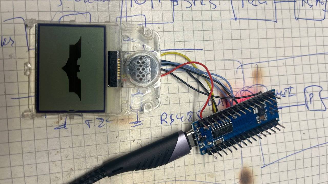
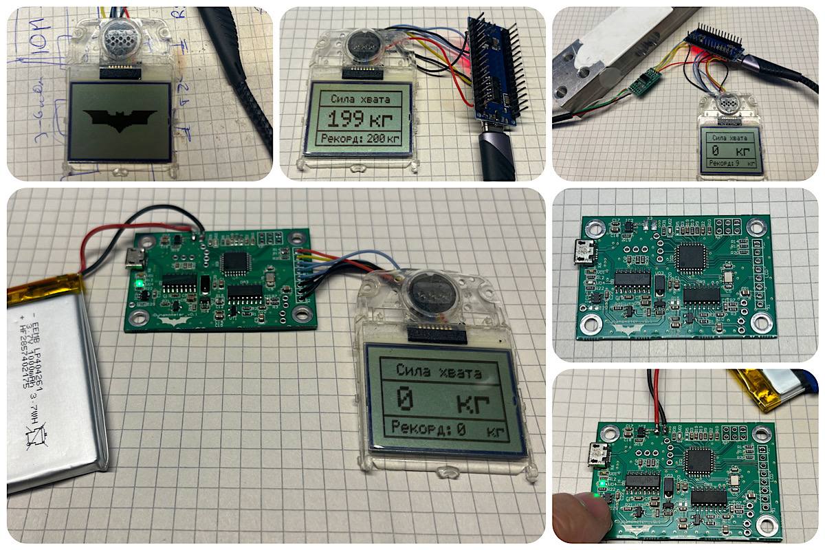
I recently came across a display from a Nokia 3310 phone and decided to get it running on an Arduino Nano. For graphics output I used the "Adafruit_PCD8544.h" library, which is designed for exactly this display driver. The resolution is 84x48 pixels. It turned out quite nice, in my opinion.
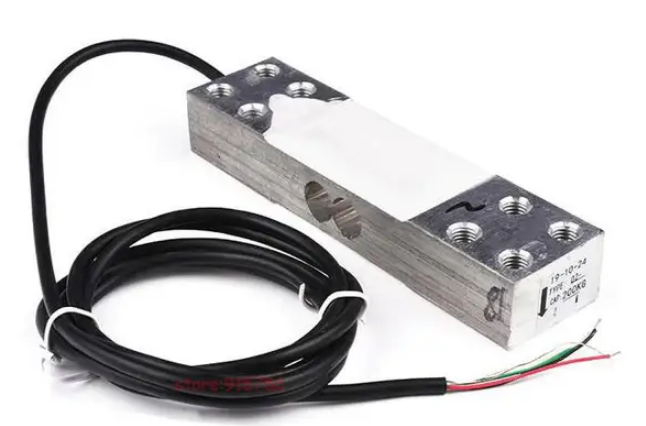
The display was just sitting around gathering dust. Ideas immediately started flowing about what it could be used for. And suddenly the idea came to build a hand dynamometer (of course, they're available for purchase, even electronic ones). I began exploring various weight sensor options for my application. The most convenient would be a tensile load cell, but its price is several times higher than a beam-type bending load cell.
When this blank arrived, I was very surprised, because I had chosen based on weight characteristics rather than dimensions, which was a mistake. The sensor length is about 145mm. Oh well, we'll work with what we have.
While the package was slowly making its way from China, I decided to make the PCB and start writing software. At that point I didn't yet know that the problem wouldn't be the hardware or software, but the enclosure and mechanical design.
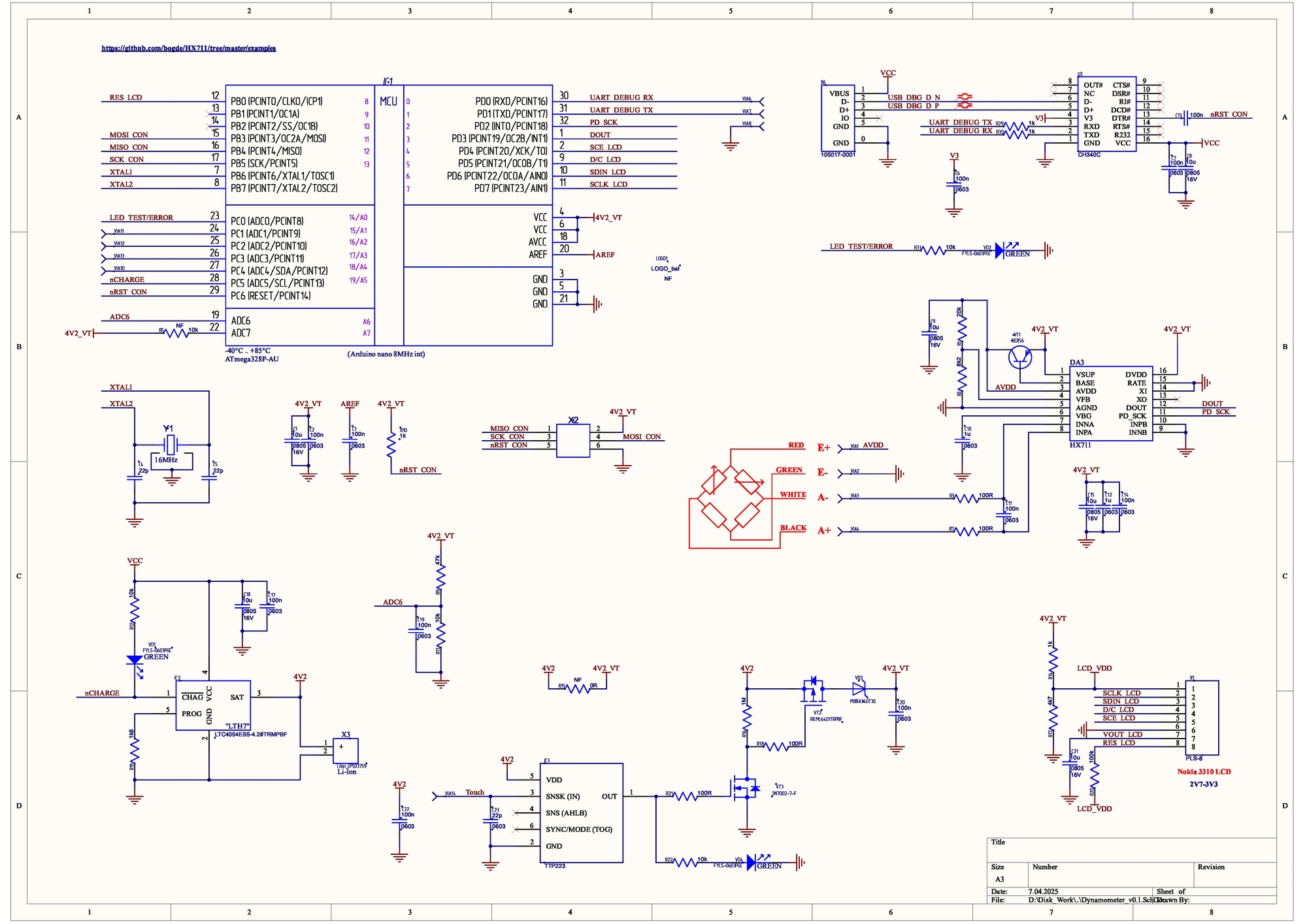
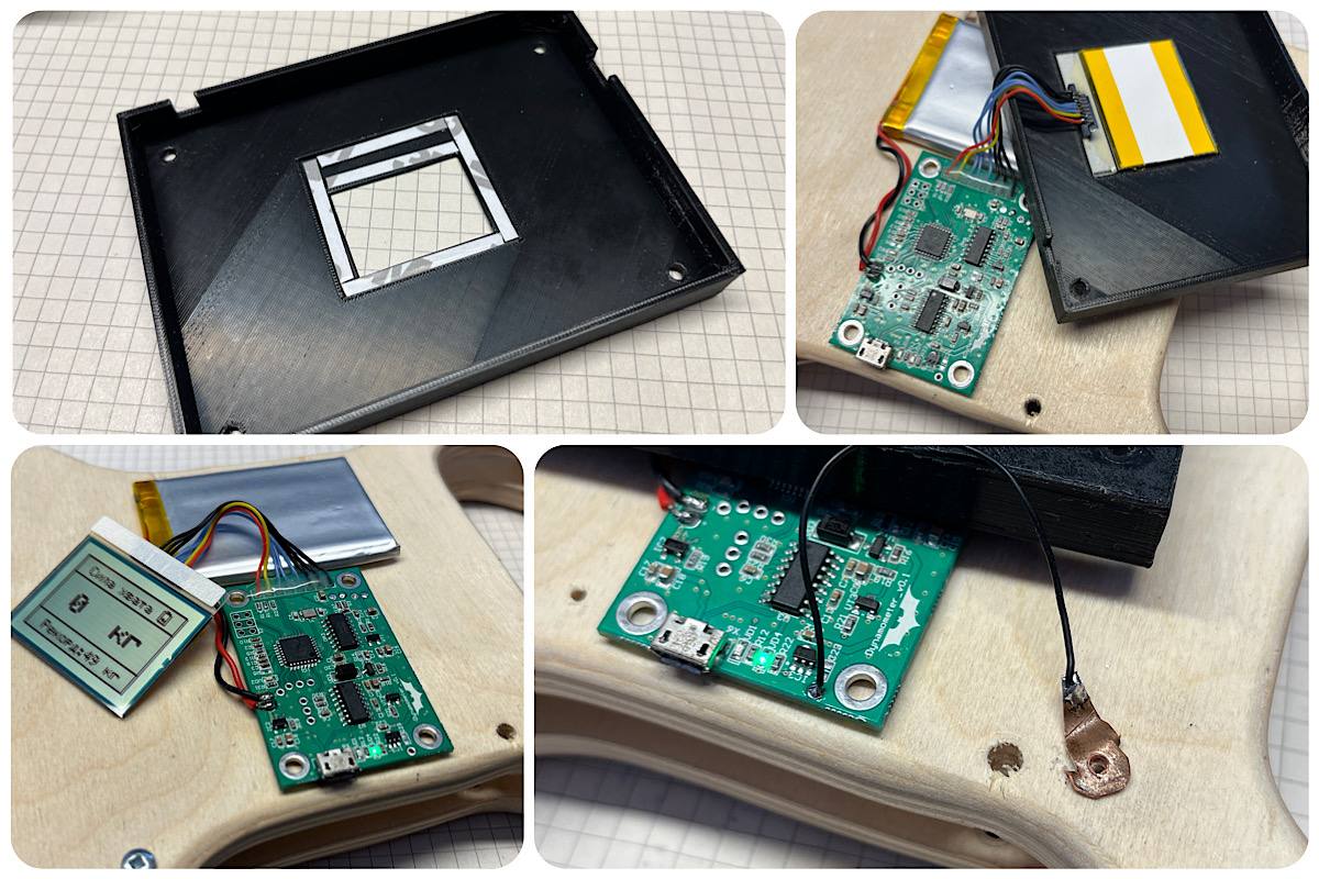
To reduce the device dimensions, I abandoned the Arduino Nano module and designed the circuit directly on the ATmega328P, while keeping the CH340C for USB programming capability. For connecting the load cell, I used the popular HX711 chip. Since this is ultimately a "wearable" device, a battery was essential. The charging circuit is built on the LTC4054ES5 (commonly known as LTH7). To avoid inventing toggle switches for power on/off (we're not putting it to sleep, after all), I decided to use a TTP223 touch sensor and cut power with an IRLML6401 transistor. Since I had all of this in module form, I prototyped it first.
To avoid boring you with tons of pictures, I made several collages to show the work process.
I used a flat 1000mAh battery. It lasts four days of continuous measurement and display. The PCB dimensions came out to 54x36mm.
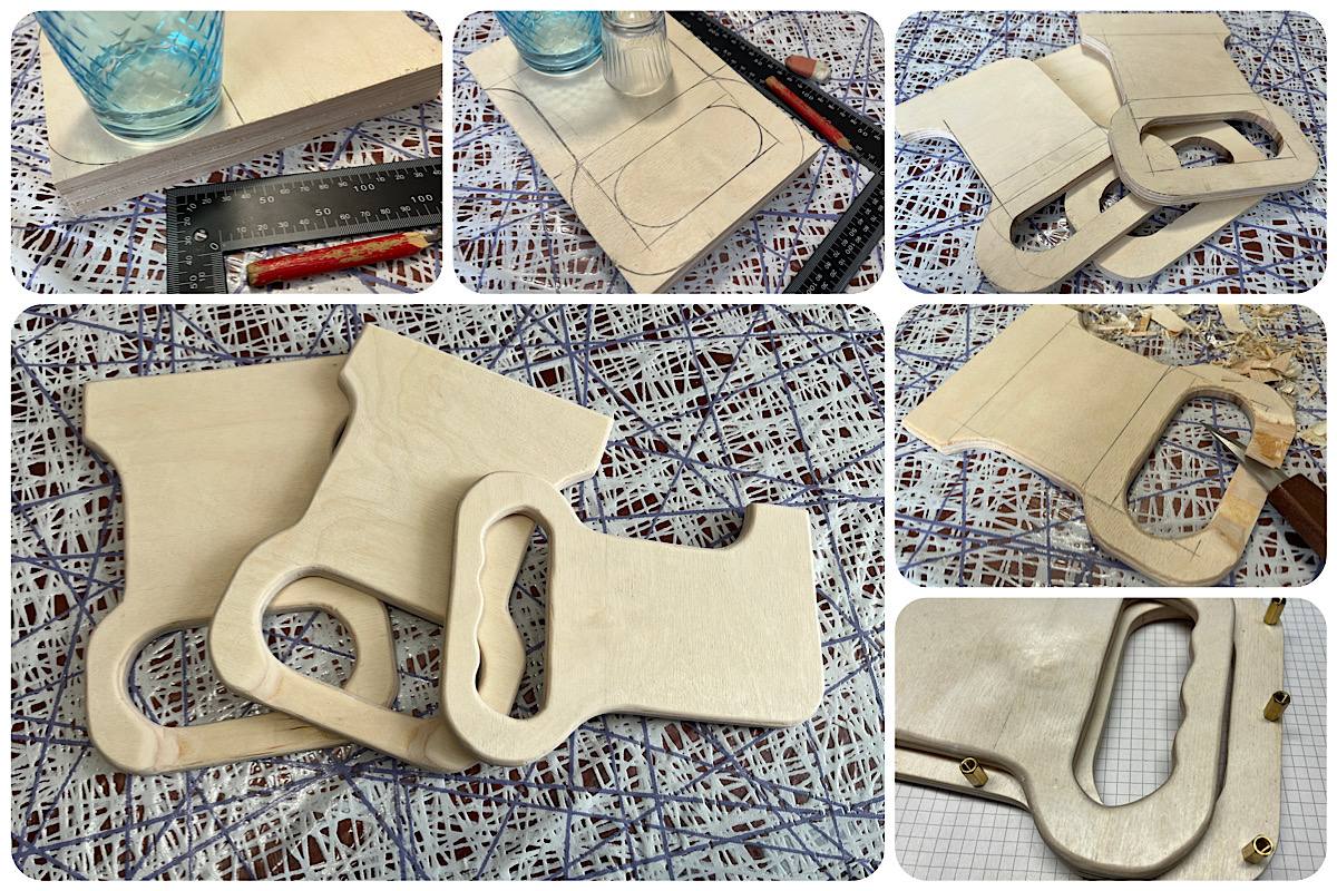
All of that is wonderful, but how do you actually make the handles for deforming the beam? We have a printer, but as I suspected, it wouldn't withstand such loads. If anyone has experience making something similar that's sufficiently durable, please share. With 3D printing, partial infill of internal cavities is usually used, such as honeycomb. Maybe you could do full infill or use some clever layer orientation. Use ribs? I don't know.
In any case, I decided to make the prototype from materials that are quick and easy to work with and modify. Once I have the final dimensions and understand the full mechanical design, I can redraw and print it. Plywood is our everything. A couple of hours with a jigsaw and knife, and everything is ready.
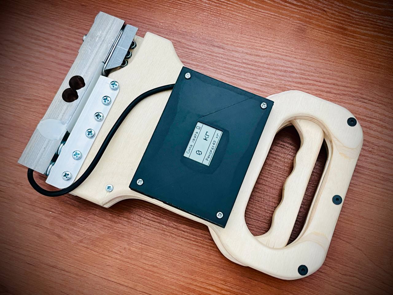
I ended up with three blanks. A pair of identical ones and a center piece that will "move" when the handle is squeezed. I coated them with furniture wax and polished a bit. It took me about a week (working evenings in my free time) to figure out how the aluminum angles would attach and how to make cutouts so nothing interfered with anything else. Initially, the angles were attached to the plywood with just two screws, but the load was too great and the holes started to loosen. In the end, only one weak point remained — the center piece connected to the angle with four screws — but it can handle my "handshake."
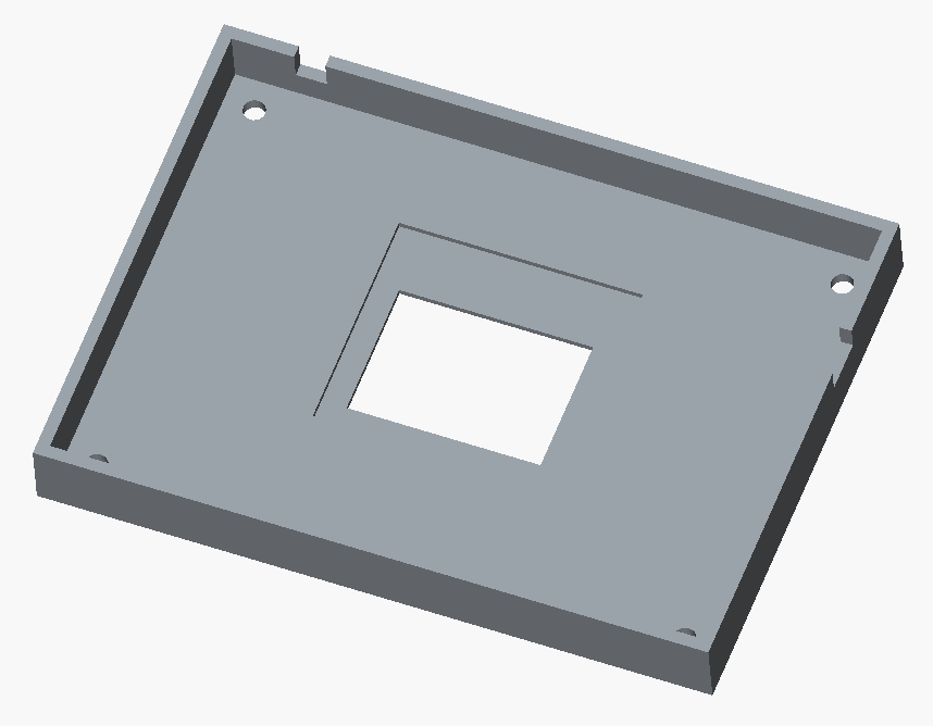
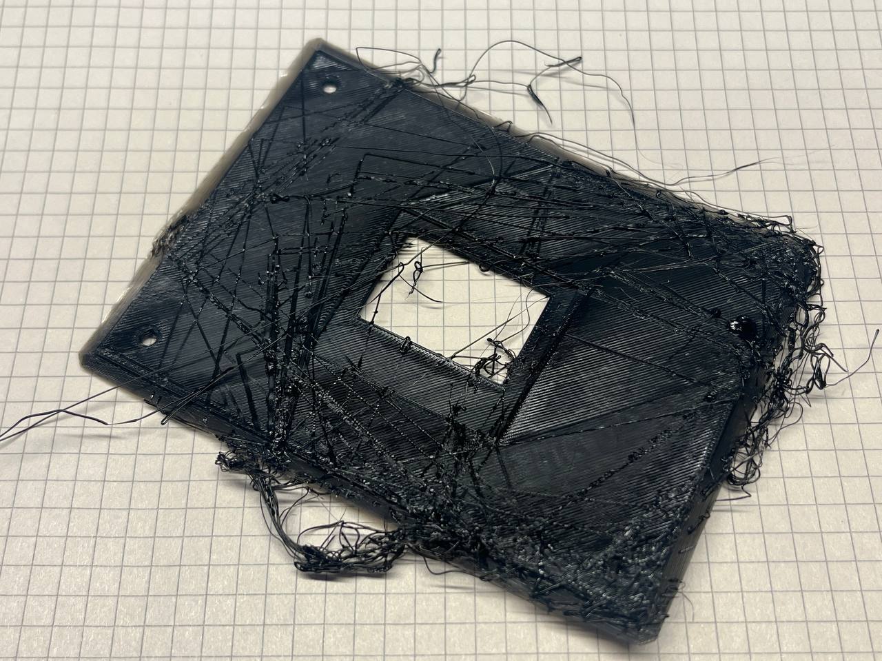
To cover the electronics, I decided to turn to the printer after all and print a cover with a cutout for the display.
I can only draw in SketchUp, and poorly at that, but overall it's quite simple and convenient. I loaded up yet another trial version of the software. Printing.

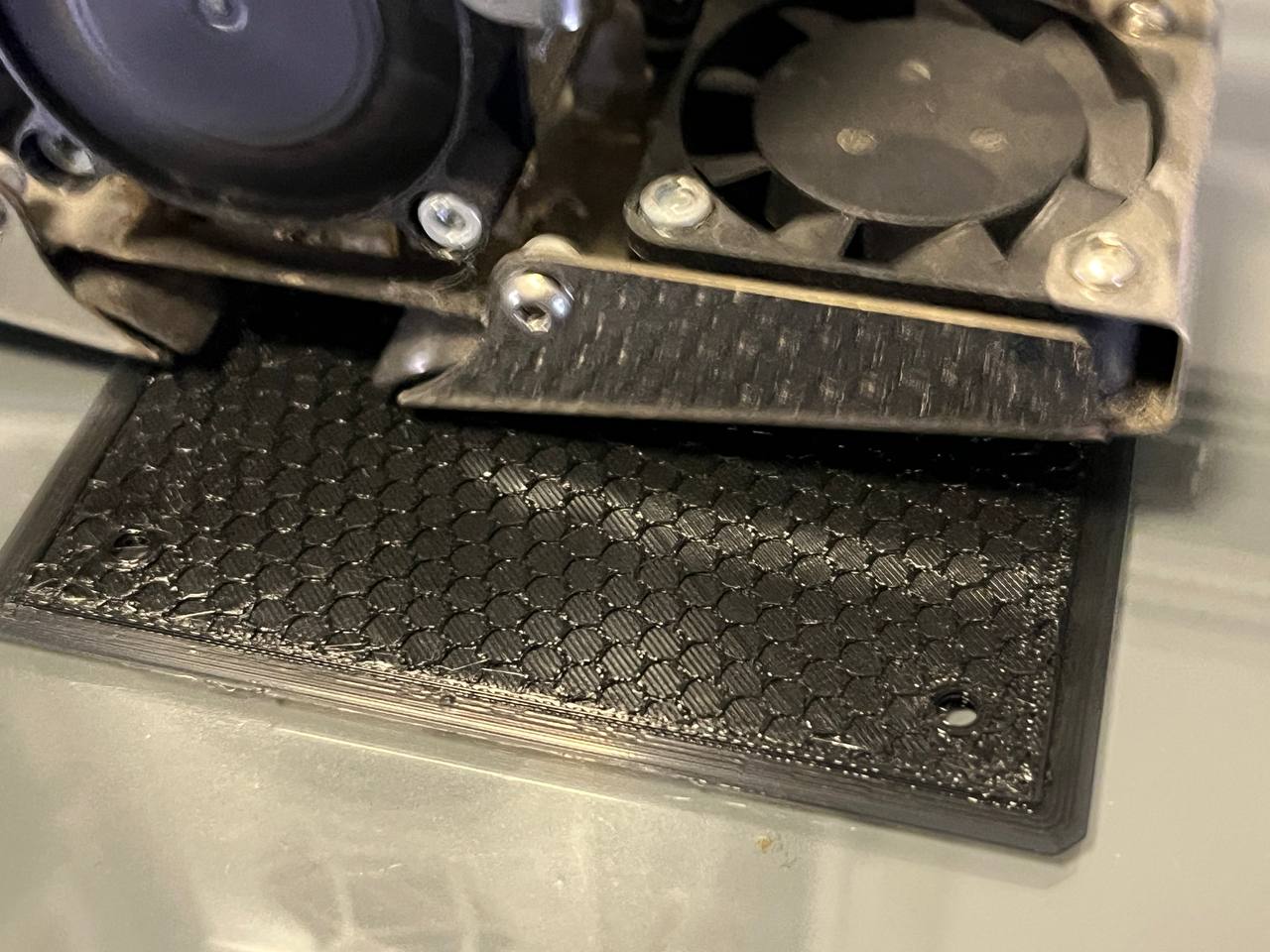
This is that infill I mentioned above. The printer lays down four layers of plastic, then honeycomb, then closes it off.
At some point the workpiece came loose and this "beard" resulted. For the next print, I applied special adhesive to the printer's glass bed. I recommend it.
I attached the display with thin double-sided tape. The contact for the touch button is made as a copper tab with a hole, through which the cover mounting screw goes. Tap the screw head — turn the device on/off.
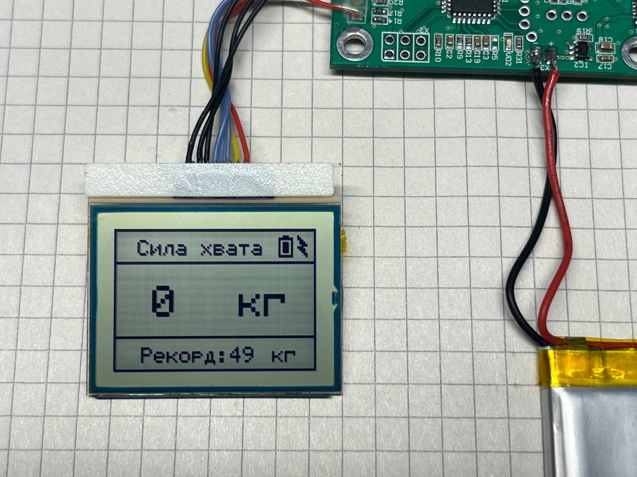
While doing all of this, I tore off the connector on the display. I found another one from a Nokia 3410. The internet says you need to use a different library for it, since its resolution is 96x65 pixels. I had already accepted that I'd need to rewrite the code, but that turned out to be unnecessary. I changed the resolution in the library source code to match mine and everything worked. I left it that way. This display is much nicer for font rendering.
I added a charging indicator as a lightning bolt in the corner. It came out looking nice.
Yes, as sad as it may be, my record is only 49 kg. Not 200, not 100, but just 49. I think the issue is with the unit conversion in the sketch (no, it isn't).
#include <SPI.h>
#include <Adafruit_GFX.h>
#include <Adafruit_PCD8544.h>
#include "HX711.h"
#include <EEPROM.h>

Adafruit_PCD8544 display = Adafruit_PCD8544(7, 6, 5, 4, 8);

#define ADC_CHARGE A6
#define TEST_LED 14
#define nCHARGE 19

int MAX_Weight = 0;
int lenght_line = 0;
float units = 0;
float ounces = 0;
int inc_ounces = 0;
int max_ounces = 0;

HX711 scale;

void setup() {
  Serial.begin(115200);
  analogReference(INTERNAL);
  pinMode(TEST_LED, OUTPUT);
  pinMode(nCHARGE, INPUT_PULLUP);
  analogWrite(ADC_CHARGE, LOW);
  display.begin();
  display.cp437(true);
  display.setContrast(60);
  display.clearDisplay();
  scale.begin(3, 2);
  if (EEPROM.read(0) > 200) EEPROM.update(0, 0);
  MAX_Weight = EEPROM.read(0);
  delay(10);
}

void loop() {
  display.clearDisplay();
  display.drawLine(80, 3, 82, 3, BLACK);
  display.drawRect(78, 4, 7, 9, BLACK);
  lenght_line = analogRead(ADC_CHARGE);
  if (lenght_line < 496) lenght_line = 496;
  if (lenght_line > 643) lenght_line = 643;
  lenght_line = map(lenght_line, 496, 643, 0, 5);
  display.drawLine(80, 10, 80, 10 - lenght_line, BLACK);
  display.drawLine(81, 10, 81, 10 - lenght_line, BLACK);
  display.drawLine(82, 10, 82, 10 - lenght_line, BLACK);
  display.drawRect(0, 0, 96, 65, BLACK);
  display.setCursor(11, 5);
  display.setTextColor(BLACK, BLACK);
  display.setTextSize(1);
  display.print(utf8rus("Grip Force"));
  display.drawLine(0, 15, 96, 15, BLACK);

  for (int i = 0; i < 10; i++) units = + scale.get_units(), 10;
  units / 10;
  ounces = units * 0.035274 / 1000;

  display.setCursor(18, 26);
  display.setTextSize(2);
  display.print((int)(ounces));
  display.setCursor(59, 26);
  display.print(utf8rus("kg"));

  if (max_ounces < ounces) max_ounces = ounces;

  if (ounces > MAX_Weight) {
    MAX_Weight = ounces;
    EEPROM.update(0, MAX_Weight);
    digitalWrite(TEST_LED, HIGH);
    delay(500);
    digitalWrite(TEST_LED, LOW);
  }

  display.drawLine(0, 49, 96, 49, BLACK);
  display.setCursor(13, 54);
  display.setTextSize(1);
  display.print(utf8rus("Record:"));
  display.setCursor(55, 54);
  display.print(MAX_Weight);
  display.setCursor(75, 54);
  display.print(utf8rus("kg"));

  if (digitalRead(nCHARGE) == 0) {
    display.fillTriangle(87, 3, 91, 7, 89, 7, BLACK);
    display.fillTriangle(89, 7, 91, 12, 87, 8, BLACK);
    display.drawLine(87, 3, 91, 12, BLACK);
  }

  if ((int)ounces > 5) { inc_ounces = 1; }

  if (((int)ounces < 5) && (inc_ounces == 1)) {
    for (int k = 0; k < 3; k++) {
      display.clearDisplay();
      display.drawRect(0, 0, 96, 65, BLACK);
      display.display();
      delay(400);
      display.clearDisplay();
      display.drawRect(0, 0, 96, 65, BLACK);
      if (max_ounces < 10) display.setCursor(39, 22);
      else if (max_ounces < 100) display.setCursor(31, 22);
      else if (max_ounces >= 100) display.setCursor(23, 22);
      display.setTextSize(3);
      display.print(max_ounces);
      display.display();
      delay(600);
    }
    inc_ounces = 0;
    max_ounces = 0;
  }
  display.display();
  delay(10);
}
The software isn't particularly complicated. We initialize the libraries (for working with the display, scales, Russian characters, and EEPROM).
At startup, we read the "record" from EEPROM to display it on screen. Since I don't need to conserve battery, I constantly refresh the entire screen in loop() (and frequently). The charge level is drawn simply based on the remaining battery voltage. I take weight sensor measurements, remember the maximum, and if the value drops below five at some point (grip released), I flash the maximum value three times on screen. If the sensor reading exceeds what's stored in EEPROM, I save it. That's it. Everything looks clean on screen with nothing superfluous, although the code itself is far from perfect.
What's noteworthy: the load cell is standard and built on a resistive bridge, where the resistance imbalance occurs due to stretching/compression of its elements. So the circuit should be standard too. I connect it, measure, and... nothing. Through trial and error (multimeter measurements were no help) I ended up with this pinout: E+ — red, E- — green, A- — white, A+ — black. Strange, but I hadn't encountered this variant before.
In the end, this is the construction I got. Bulky, lots of screws, angles, and plywood, but fully functional.
Thank you for your attention, and good luck!
FAQ
What is this article about in one sentence?
This article explains the core idea in practical terms and focuses on what you can apply in real work.
Who is this article for?
It is written for engineers, technical leaders, and curious readers who want a clear, implementation-focused explanation.
What should I read next?
Use the related articles below to continue with closely connected topics and concrete examples.