How I Built a Quadcopter on ESP32 from Scratch (It Took 4 Years)
In 2019, the author set out to build a quadcopter without any off-the-shelf flight controller or firmware. After four years of development, the result is a stable, flying drone based on ESP32 with open-source code that anyone familiar with Arduino can understand.
When building quadcopters and other UAVs, people typically use a ready-made flight controller board containing all the necessary sensors and peripherals, along with ready-made flight firmware such as Betaflight, ArduPilot, or PX4. The flight controller manages the quadcopter's motors and ensures stable flight.
In 2019, I took on a rather ambitious task — to create a quadcopter without using a ready-made flight controller board or ready-made firmware, essentially implementing everything from scratch. Then I planned to document this process as a textbook on the theory and practice of developing UAV flight controllers. After four years, I managed to develop a stably flying quadcopter based on the ESP32 microcontroller and the Arduino platform, and even gained some traction for the project.
The project's source code and all materials are published on GitHub: github.com/okalachev/flix. In this article, I'll break down what my drone is made of and how its firmware works.
A quadcopter flight controller firmware is quite complex software that may include advanced algorithms from control theory. Such firmware is written by entire research groups and companies. For example, the source code of the PX4 firmware, even without submodules, contains about 400,000 lines of C++ code. This code is difficult to understand and not suitable for learning the basic principles of UAV flight control.
I created firmware with the simplest possible coding style, so that anyone slightly familiar with Arduino could understand it. It has already been used as a teaching aid in a flight controller programming course at the Moscow Aviation Institute (MAI).
Currently, my firmware consists of 17 C++ files, each averaging about 60 lines of code. The firmware is very easy to compile and upload to the ESP32 using either the Arduino IDE or the command line. Build instructions are in the project repository.
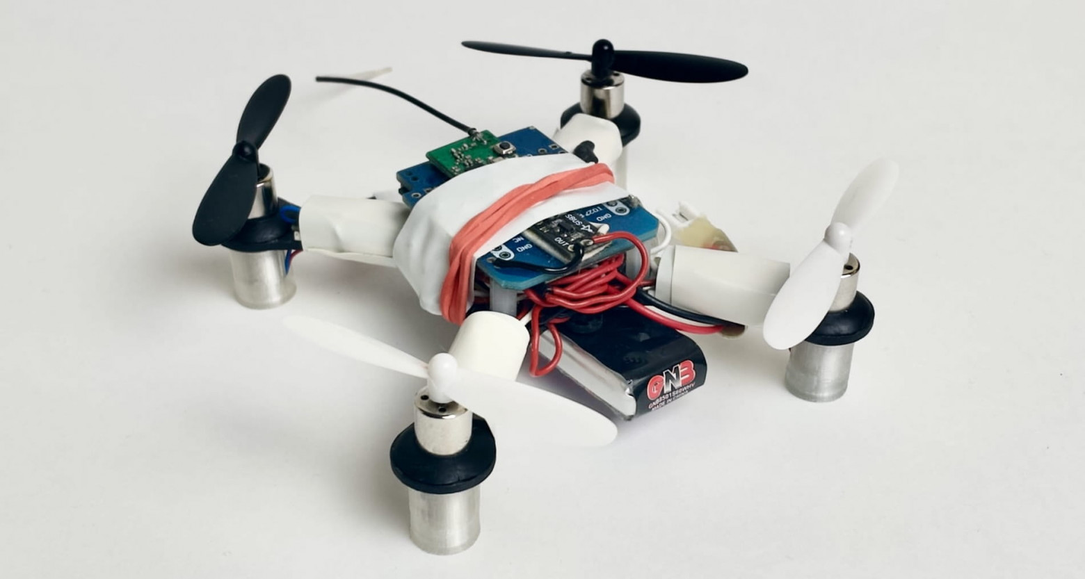
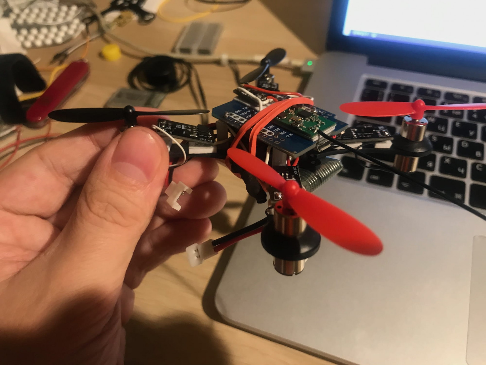
I also assembled a miniature quadcopter that includes all flight controller components, but separate from each other.
Choosing the Hardware
When selecting hardware, I prioritized universal components over quadcopter-specific ones. I believe this is the way to truly understand how something works at a deep level. Cost and availability in various markets were also important factors.
Microcontroller
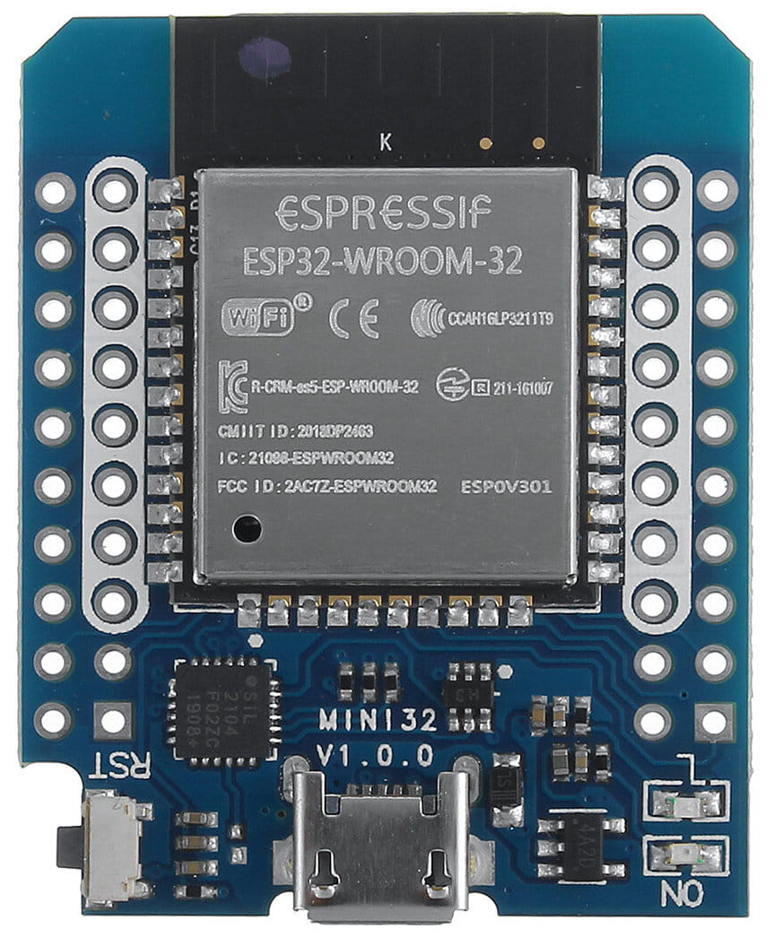
The central component of the flight controller is the microcontroller, and most commonly these are STM32-family microcontrollers. I decided to go with a more unconventional ESP32 microcontroller in the form of an ESP32 Mini board. This Chinese microcontroller has more resources than something like the STM32F4 while being cheaper. But its main feature is built-in Wi-Fi and Bluetooth. Over Wi-Fi, you can set up communication between the quadcopter and a ground station: receive telemetry and send commands, as well as control it using a smartphone, which I implemented.
Sensors
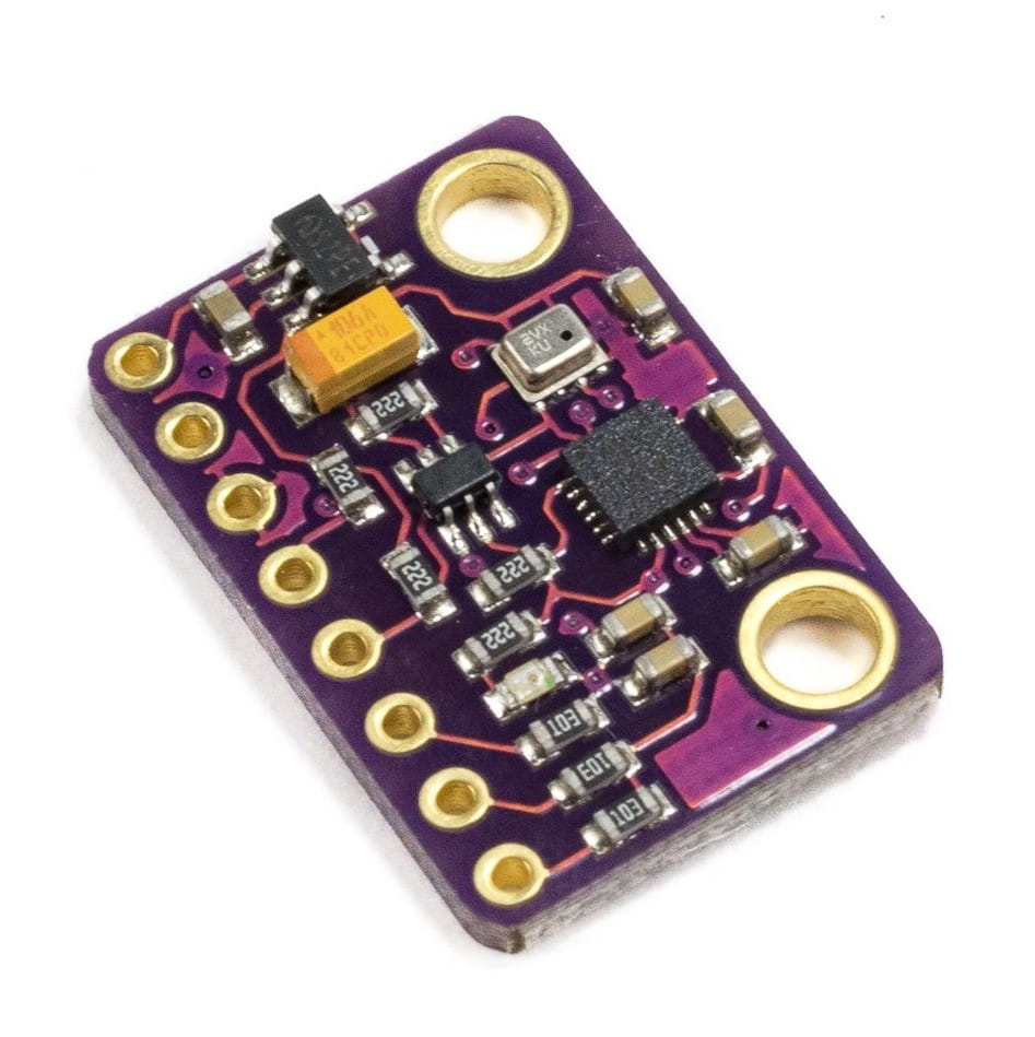
The minimum set of sensors needed for stable quadcopter flight is a gyroscope and accelerometer. These two sensors (and sometimes a magnetometer) are typically combined into a single chip called an Inertial Measurement Unit, or IMU. For my quadcopter, I used the InvenSense MPU-9250 IMU. The IMU connects to the microcontroller via the SPI bus.
RC Receiver
To receive signals from the control transmitter, a standard 2.4 GHz RC receiver is used, communicating with the transmitter via the Futaba S-FHSS radio protocol. The receiver connects to the microcontroller through the Futaba SBUS interface, which is essentially a regular UART with an inverted RX signal. Fortunately, the ESP32 supports UART signal inversion in hardware and has available UART interfaces, so connecting the receiver poses no issues.
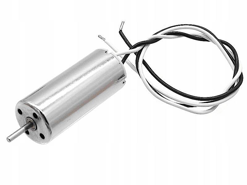
Motors
I used brushed motors of the 8520 form factor (8.5 mm by 20 mm), commonly used in miniature quadcopters. They are much cheaper than brushless motors and simple to control — they connect to the microcontroller through a MOSFET and are driven by a PWM signal. However, in the first version, for simplicity, I used a ready-made motor driver module from AliExpress, but in future versions I plan to switch to a simple transistor.
Frame
To mount all the components, I used a standard 100mm carbon frame from AliExpress, suitable for the motors I chose. The next version I plan to build on a custom frame printed on a 3D printer that will better accommodate the components described above.
Power
The quadcopter is powered by a single-cell lithium polymer battery with a nominal voltage of 3.7V. I selected a battery with a high discharge rate so there would be enough current for both the motors and the microcontroller with Wi-Fi, IMU, and RC receiver. The ESP32 runs on 3.3V, but the ESP32 Mini and GY-91 boards have built-in LDO voltage regulators that allow powering them directly from the battery.
Assembly
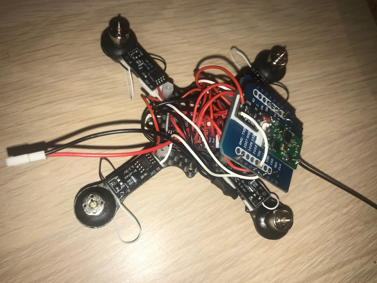
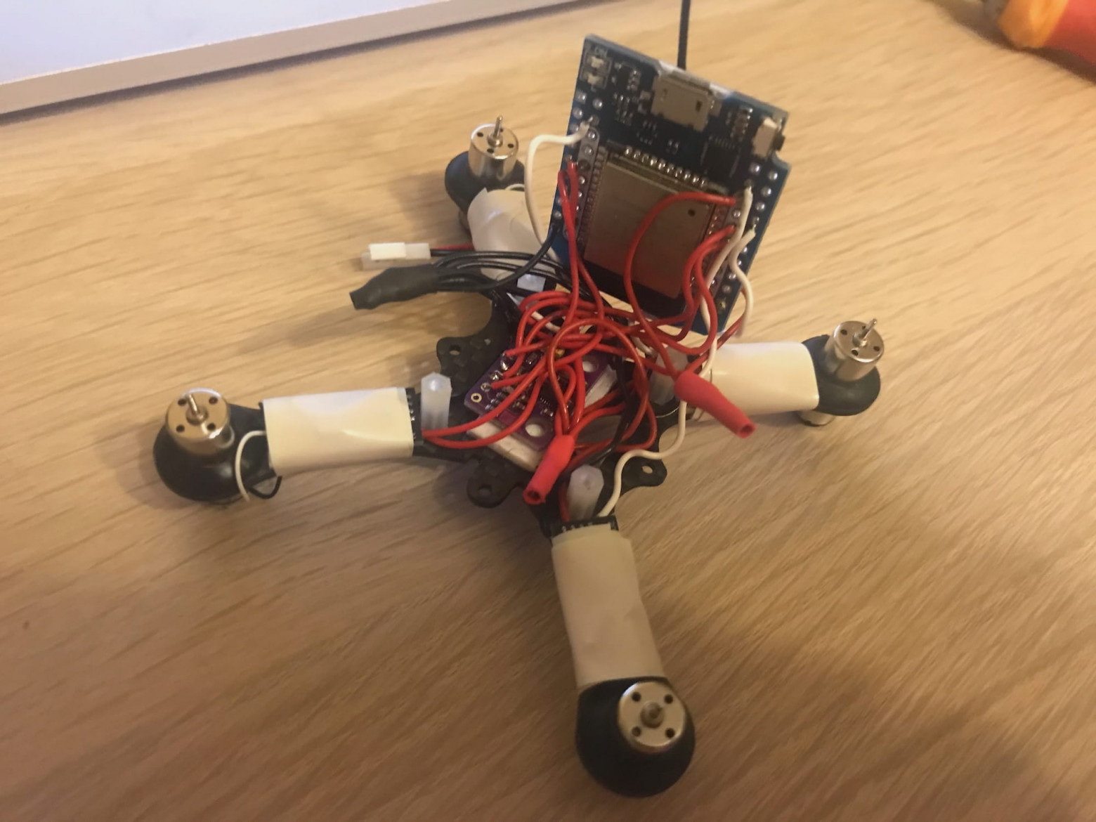
Armed with a soldering iron, a roll of silicone wire, and double-sided tape, I assembled my drone. The process took about a week.
In the photos you can see the microcontroller, IMU module, RC receiver, and motors. Everything is connected with wires and mounted on the frame.
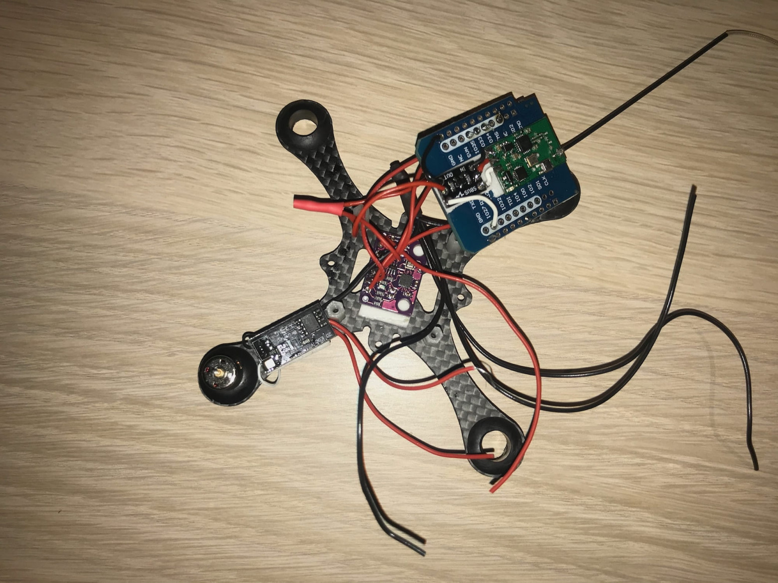
A complete list of components used in the current version can be found in the corresponding list in the project repository. There's also a link to the full wiring diagram.
After assembly, I moved on to the hardest stage — developing and debugging the flight firmware. And this stage dragged on for years. But in the end, I succeeded. Below I'll cover the general quadcopter control algorithm and how I implemented it.
Quadcopter Control Algorithm
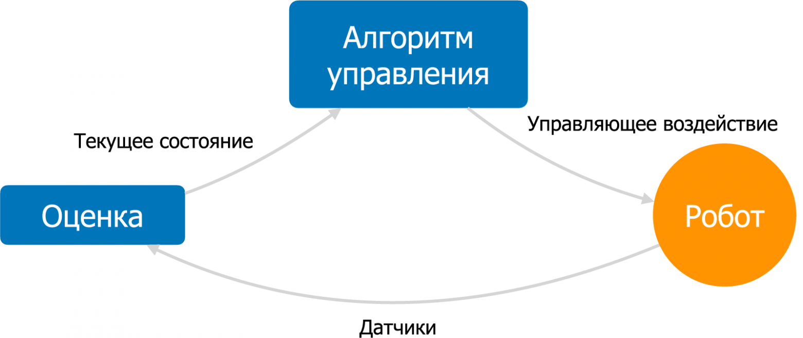
A quadcopter is not a self-stabilizing aircraft, and a fairly complex control algorithm is needed for it to fly. The goal of this algorithm is to maintain stable flight according to the pilot's commands: for example, maintaining a given orientation, speed, or position. An automatic control algorithm with feedback is used for this. This algorithm consists of a state estimation subsystem and a control subsystem.
The state estimation subsystem uses sensor data to calculate the quadcopter's current state as accurately as possible: angular velocity, orientation, linear velocity, position, and other parameters.
The control subsystem takes as input the current state and the desired state, also called the setpoint. Based on the difference between the current and desired state, the control algorithm calculates the control action — signals to the motors. The goal of the control action is to bring the drone to the desired state as efficiently as possible. This algorithm runs in an infinite loop at a high frequency.
In my firmware, the standard Arduino loop function implements this cycle, sequentially performing sensor reading, state estimation, control, and service functions. At the beginning of each iteration, the blocking function readIMU is called, which ties the main loop frequency to the IMU sensor frequency, configured at 1000 Hz. The main loop is in the file flix.ino.
State Estimation Subsystem (file estimate.ino)
The estimation subsystem implements the classic algorithm for estimating an object's orientation using a gyroscope and accelerometer — the complementary filter.
This algorithm calculates a weighted sum between the orientation obtained by integrating angular velocities from the gyroscope and the direction of the gravity vector obtained from the accelerometer. This way, the advantages of both sensors are utilized while compensating for their drawbacks: gyroscope drift during integration, and the noise and vibration sensitivity of the accelerometer.
The outputs of the estimation subsystem are the filtered angular velocity along three axes (variable rates) and the current orientation of the quadcopter (variable attitude). Orientation is represented as a quaternion, which is the standard way of representing orientation in robotics.
Control Subsystem (file control.ino)
The control subsystem takes as input the drone's state and the position of the sticks on the pilot's transmitter. The task is to calculate control signals for the motors.
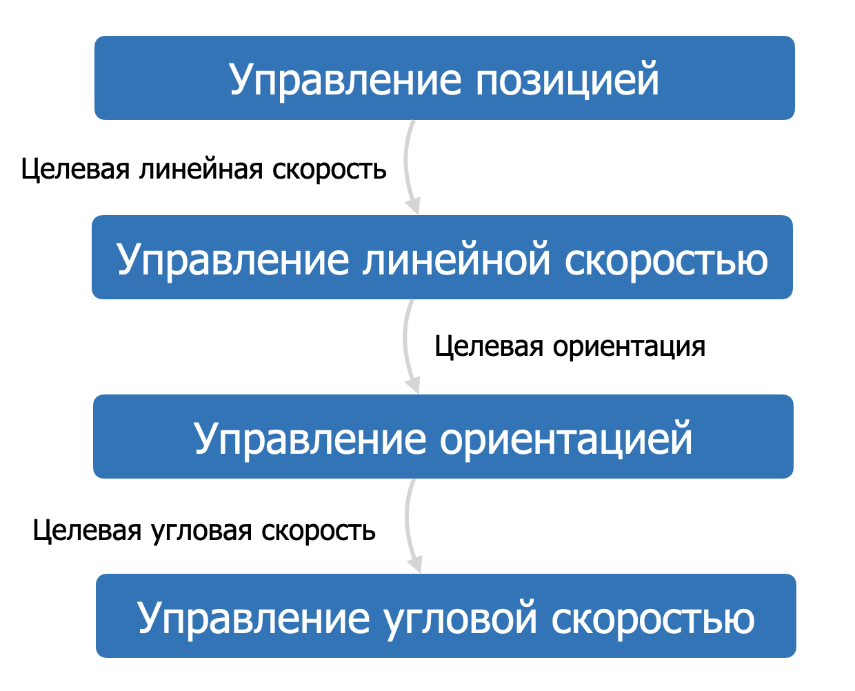
The standard quadcopter control algorithm includes several sub-levels, also called control loops. Each loop is responsible for a specific aspect of flight: position, velocity, orientation, angular velocity. Together they form a so-called cascade, where the input of each subsequent loop is the output of the previous one. For example, for a drone to fly forward — to acquire linear velocity, it needs to tilt forward — change orientation, and to change orientation, it needs to change angular velocity.
I implemented the two lowest levels of this cascade: orientation control and angular velocity control. This allows the pilot to fly in orientation stabilization mode. In this mode, the right stick of the transmitter controls the quadcopter's tilt, and the left stick controls the overall throttle level and rotation around the vertical axis. In different drones, this mode may be called horizon hold, "LEVEL," "ANGLE," or "STABILIZE." In my drone, this mode is called STAB.
There is also the option to switch to angular velocity control mode (ACRO), which uses only the lowest level of the control cascade. This mode is much harder to pilot and is typically used in racing and for performing tricks.
Angular Velocity Control
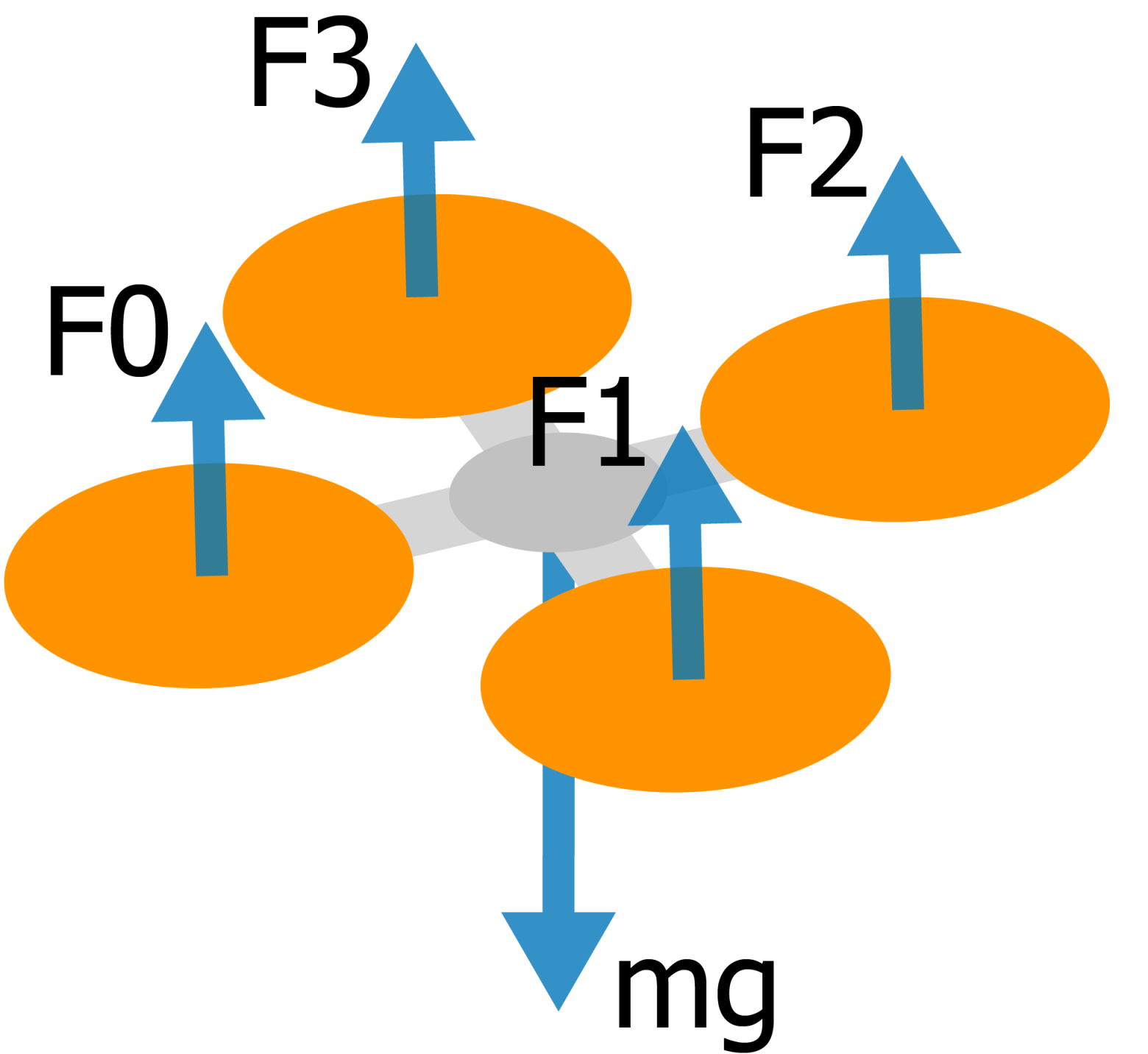
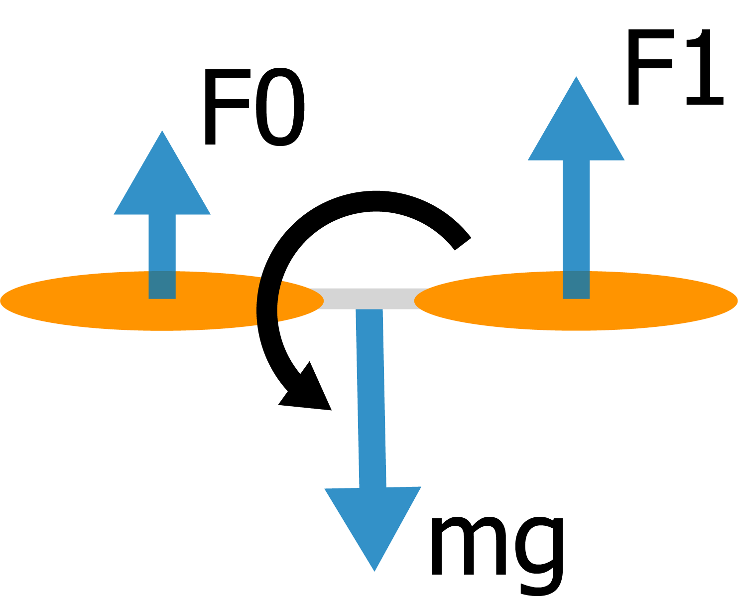
Let's start examining the cascade from the lowest level. The task of this level is to take the required angular velocities as input and calculate control signals for the motors. To understand how to calculate control signals, let's look at the force diagram acting on the quadcopter.
From the diagram, we can see that the quadcopter is affected by gravity and four propeller thrust forces that must compensate for it. But if we create a "bias" in thrust between pairs of propellers (front-rear, left-right), we can create a torque that will change the quadcopter's angular velocity.
This torque will be linearly dependent on the thrust difference between propellers. By controlling this difference, we can control the longitudinal and lateral angular velocity of the quadcopter.
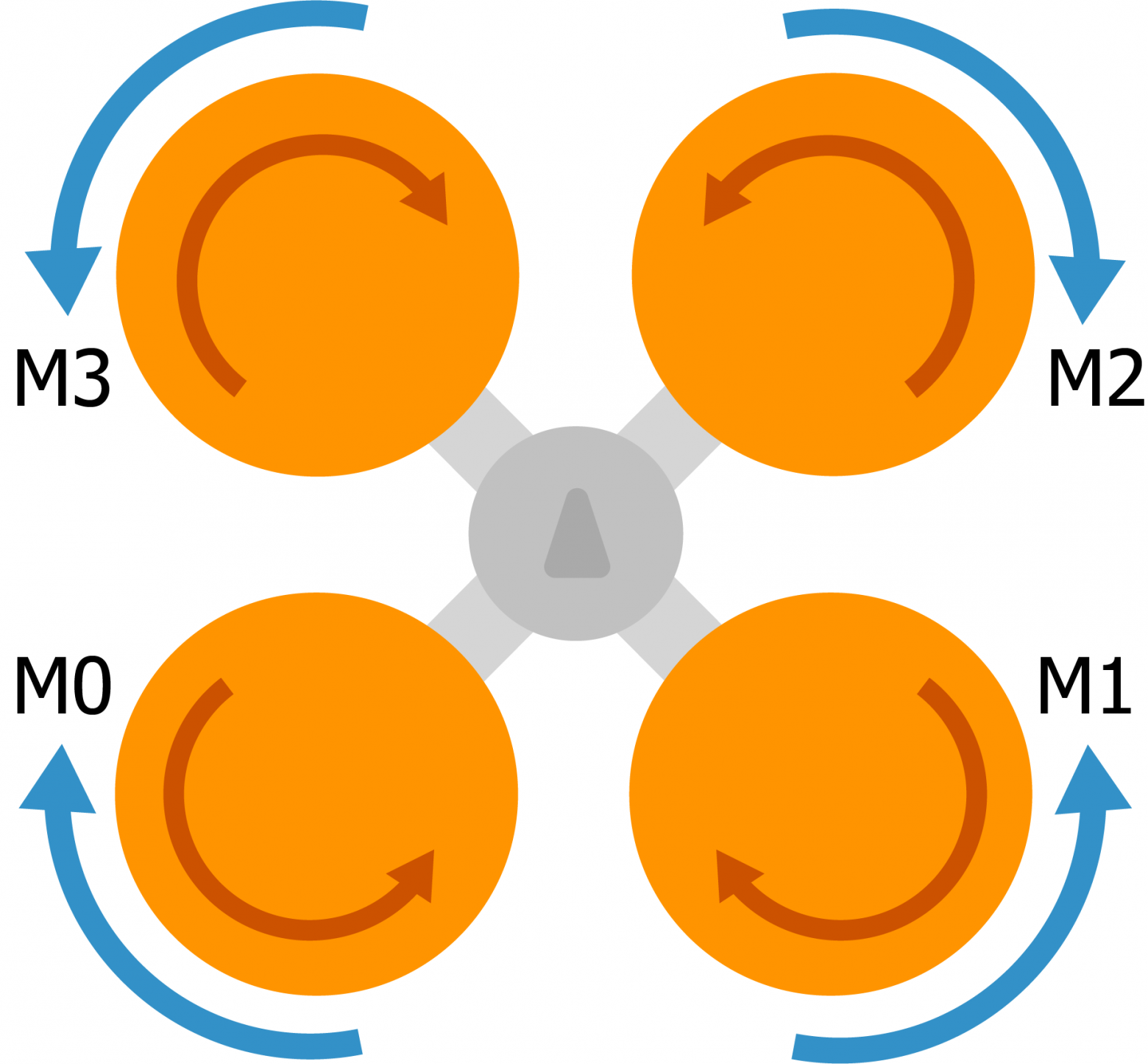
Angular velocity control around the vertical axis (yaw) is implemented differently — it uses the fact that each motor, in addition to spinning the propeller, slightly rotates the quadcopter itself in the opposite direction. The rotation directions of propellers are different, and if one diagonal pair of propellers spins faster than the other, the quadcopter will rotate around the vertical axis.
So if we place the required torques in the vector torqueTarget and the total required thrust in the variable thrustTarget, the control signals for the motors can be calculated as simple sums:
motors[MOTOR_FRONT_LEFT]  = thrustTarget + torqueTarget.y + torqueTarget.x - torqueTarget.z;
motors[MOTOR_FRONT_RIGHT] = thrustTarget + torqueTarget.y - torqueTarget.x + torqueTarget.z;
motors[MOTOR_REAR_LEFT]   = thrustTarget - torqueTarget.y + torqueTarget.x + torqueTarget.z;
motors[MOTOR_REAR_RIGHT]  = thrustTarget - torqueTarget.y - torqueTarget.x - torqueTarget.z;
This set of formulas is called a mixer, and it effectively defines the UAV configuration. For example, for a hexacopter (with six propellers) the mixer would be different, but the main control algorithm would remain the same. The mixer is implemented in the controlTorque function.
Now, knowing the current angular velocities and required angular velocities, we need to calculate that required torque torqueTarget.
P-Controller
In the ideal case, to calculate torqueTarget we simply compute the control error — the difference between the required angular velocity and the actual one — and multiply it by some arbitrarily chosen proportional coefficient p, which determines the "aggressiveness" of the quadcopter's response:
torqueTarget = p * (ratesTarget - rates);This control algorithm is called a proportional controller or P-controller. But in practice, two problems arise:
- First, motors have inertia and cannot instantly change their rotation speed. Because of this, controlling with a simple P-controller results in overshoot and oscillations.
- Second, all motors differ slightly from each other and are not perfectly positioned on the frame. This causes a static control error, or simply put, constant unwanted rotation of the quadcopter around some random axis.
The simplest way to solve these problems is a PID controller.
PID Controller (file pid.h)
Instead of one coefficient for controlling the system, the PID controller introduces three: proportional, integral, and derivative. These three coefficients are manually tuned during system tuning.
The derivative coefficient d is multiplied by the derivative of the control error, thus implementing anticipation in system control. This solves the problem of system inertia.
The integral coefficient i is multiplied by the integral of the control error and solves the static control error problem. After a couple seconds of flight, this value "accumulates" and becomes exactly equal to the static error, compensating for it.
In simplified form, a PID controller in C++ looks like this:
integral += error * dt;
control_action = p * error + i * integral + d * (error - prevError) / dt;
You can understand its operation more intuitively on a specially created demo page.
In the end, three independent PID controllers are applied for angular velocity control for each axis: rollRatePID, pitchRatePID, and yawRatePID. The function controlRates handles these three controllers.
Orientation Control
The orientation control loop takes as input the required orientation (set by the pilot), the current quadcopter orientation, and calculates the required angular velocity ratesTarget. The error calculation here is more complex. A special kinematic formula is used, implemented in the function angularRatesBetweenVectors. This error vector then feeds into three PID controllers: rollPID, pitchPID, and yawPID. However, the integral and derivative components are not used (I = D = 0), since in practice they aren't necessary for stable flight, so these are effectively simple P-controllers.
This loop is implemented in the function controlAttitude. According to the cascade, the output of this loop feeds into the previously described controlRates function.
Result
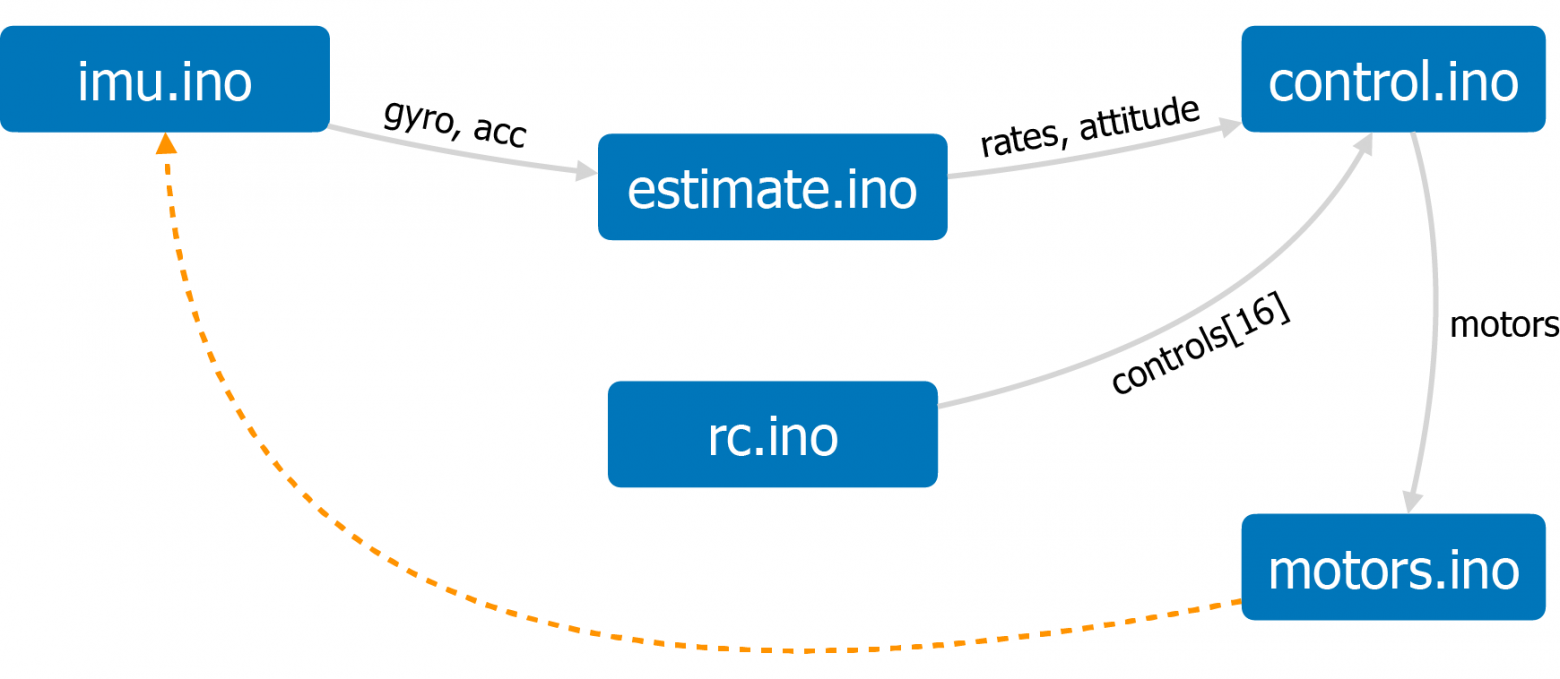
By combining the subsystems described above, and adding service functions — sensor data reading (imu.ino), transmitter stick position reading (rc.ino), and motor control signal output (motors.ino), in theory we get a stably flying quadcopter controllable from a transmitter. And in practice, after many months of debugging, we get one too.
To summarize, here's a link to the full algorithm diagram that I implemented using the D2 language: flight control diagram.
The project repository also has a brief overview of the firmware architecture.
Why Development Took So Long
The main problem with developing firmware for a quadcopter is the extremely difficult debugging of a flying vehicle. After all, you can't "pause" a flying drone to analyze its state. For most of the development time, the drone did nothing resembling stable flight. When attempting to take off, it would either instantly flip over or take off, enter wild oscillations, and immediately crash into the nearest wall. Typically, after several hours of such debugging, I'd lose motivation and abandon the project for months.
Adding state logging to the microcontroller's RAM helped, with subsequent downloading and analysis of logs. However, the turning point was developing a simulator based on the Gazebo environment. It was precisely after step-by-step debugging of the algorithm in the simulator that the first more or less stable flight was achieved on the drone.
The main reasons why the quadcopter didn't fly or flew poorly:
- Due to incorrect IMU configuration, the actual update rate of gyroscope and accelerometer data was not 1000 Hz but 50 Hz. Such frequency is critically insufficient for stabilizing a quadcopter.
- The PWM signal update rate for the motors was also low — 50 Hz. Increasing the frequency to 200 Hz significantly improved flight stability.
- In the original build, motors with incorrect supply voltage were used by mistake — 6V instead of 3.7V. As a result, when the quadcopter's algorithm was relatively debugged, the quadcopter was catastrophically underpowered and could only fly for the first 20-30 seconds after a full battery charge.
- Lack of D-component filtering in the PID controller. The D-component is extremely sensitive to noise, so it needs to be filtered. In the original algorithm version, there was no such filtering, which caused very severe oscillations during flight. After adding a low-pass filter, flight became stable.
- Many other critical errors and inaccuracies in the control algorithm that were debugged through simulation.
Additional Features
Besides flying with a transmitter, my drone has a number of additional features. It partially implements communication via the MAVLink protocol — a popular protocol for interacting with UAVs. This allows connecting to it over Wi-Fi and viewing telemetry using the QGroundControl application. Additionally, using the mobile version of this application, you can control the drone from a smartphone.
Also, as already mentioned, the drone has a full-fledged simulator built on the Gazebo simulation environment. The simulator runs the actual firmware code, simulating the operation of sensors and motors, and partially emulating the Arduino API. The simulation code and build instructions are also available in the project repository, and anyone can run it on their computer (Ubuntu / macOS).
The topic of simulation deserves a separate article. Here I'll only provide a link to a post in the Telegram channel that describes the architecture of my drone's simulator.
Project Blog and Future Textbook
If you're interested in the project, you can follow the blog on Telegram, where all project news is published, as well as posts about flight controller development and UAVs in general. Like, for example, this post that describes in detail how the automatic flip maneuver was implemented on my drone.
If this article does well, I can write other articles on the topic of UAV flight controller development — there's certainly plenty to talk about. However, I plan to place the main content in the project blog, as well as in a future textbook on flight controller development, for which I created this drone, although for my own education as well, of course.
I'll be happy to answer any questions and comments. Thank you for reading!