How to Transmit a Signal Over a Cable Correctly
A practical guide to electrical signal transmission over cables, covering noise reduction techniques including shunting, differential signaling, shielding, and galvanic isolation with real oscilloscope measurements.
Introduction
This article examines different methods of transmitting electrical signals over cables while minimizing interference and noise. Whether you're working with audio equipment, industrial sensors, or digital communication, understanding these principles will help you choose the right approach for clean signal transmission.
Basic Signal Transmission Options
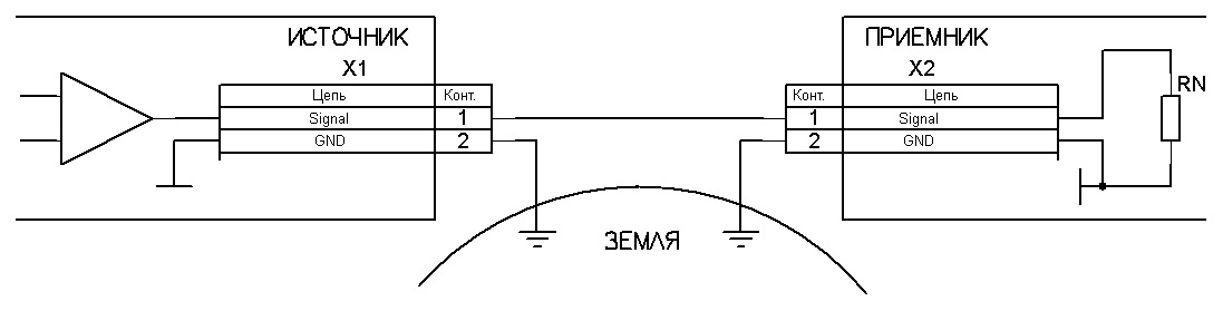
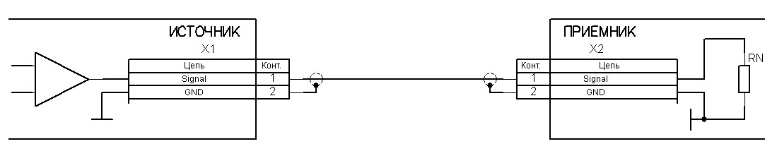
Two-Wire Transmission
The most basic method requires a signal wire and a common wire (GND). The common wire goes by many names: zero, ground, minus, chassis, or mass. This configuration is susceptible to electromagnetic interference because the loop formed by the two wires acts as an antenna that picks up external noise.
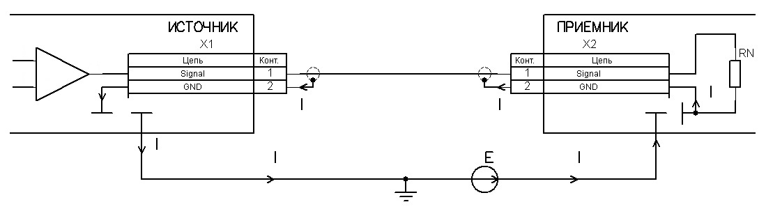
Single-Wire Transmission
This approach uses metallic structures as the second conductor — the device chassis, earth ground, or a car body. While it saves on wiring, it introduces additional noise sources since the return path through metal structures picks up interference from other circuits sharing the same conductor.
Methods for Fighting Interference
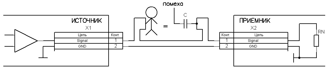
1. Shunting (Impedance Reduction)
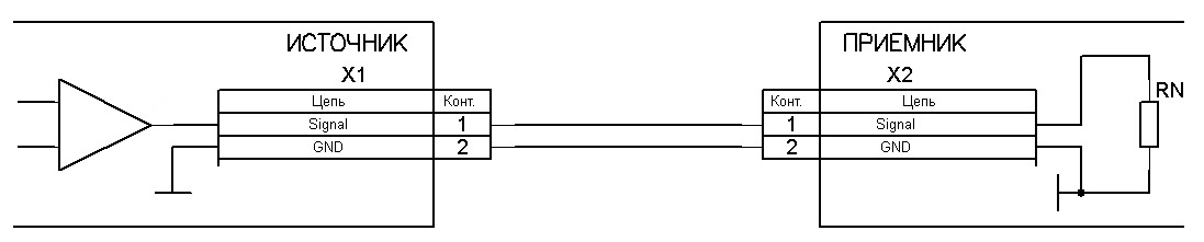
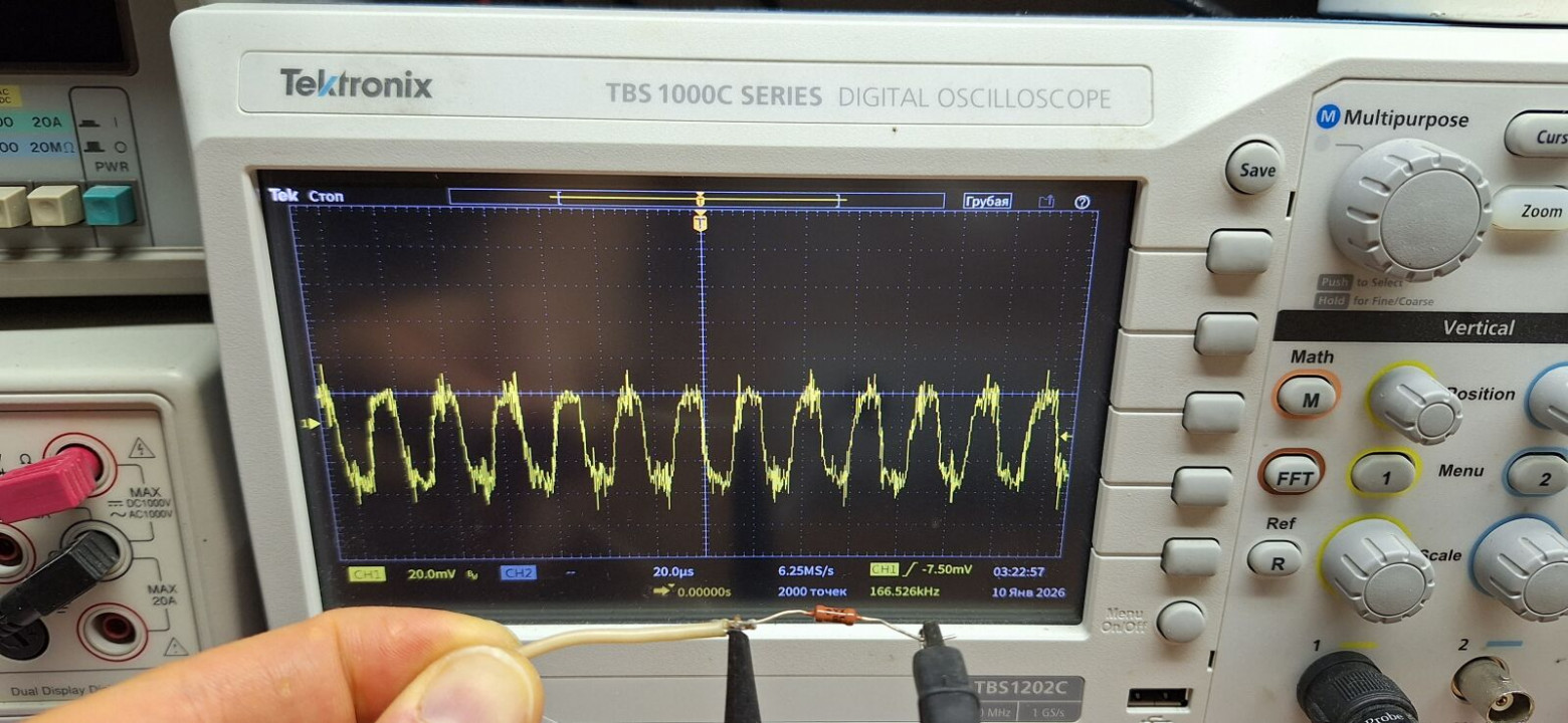
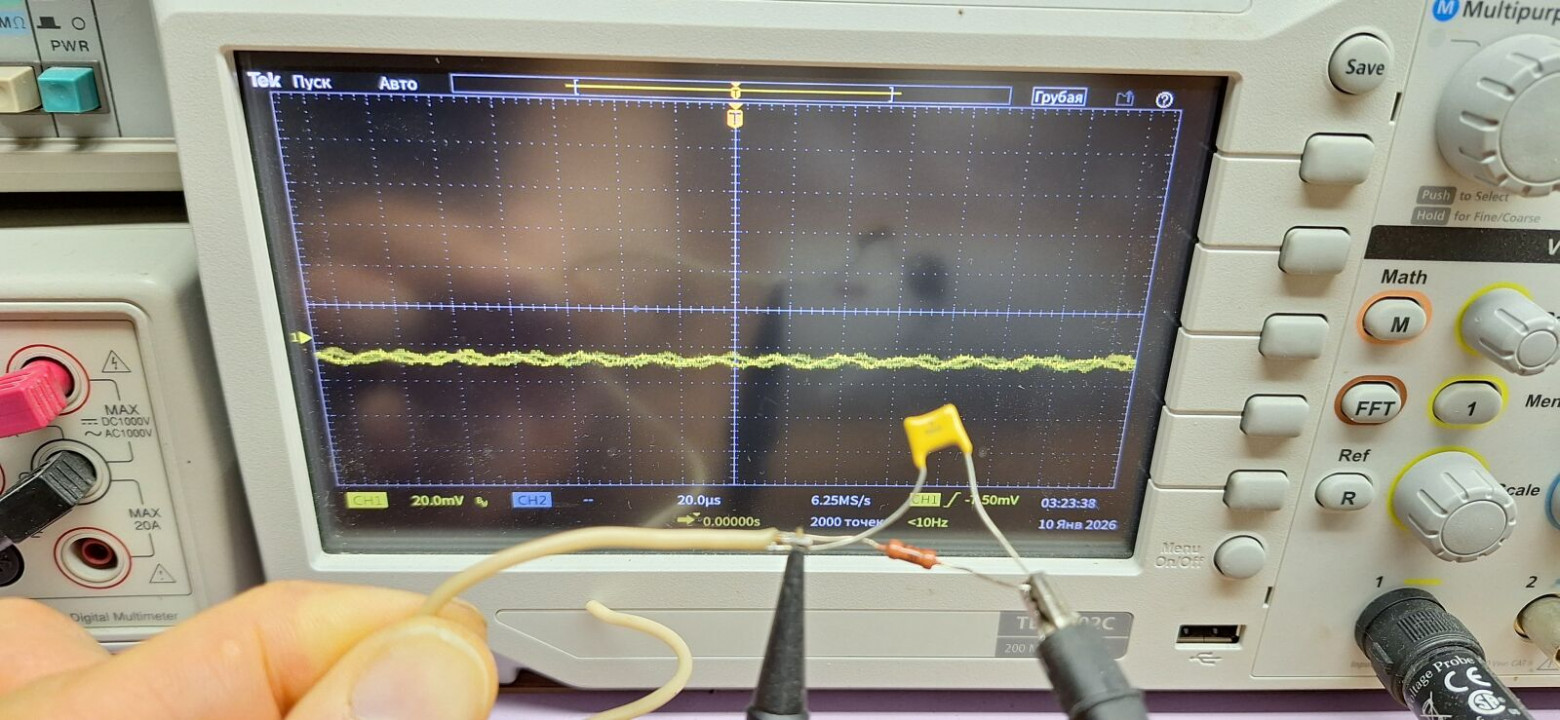
By reducing the input and output impedances of the source and receiver, you reduce the voltage that interference can develop across them. In professional audio equipment, the standard impedance is 600 Ohms. Even adding a simple 10 kOhm resistor across the input can substantially reduce induced noise.
The principle is straightforward: noise voltage is proportional to the impedance it acts upon. Lower impedance means lower noise voltage, even if the noise current remains the same.
2. Differential Transmission
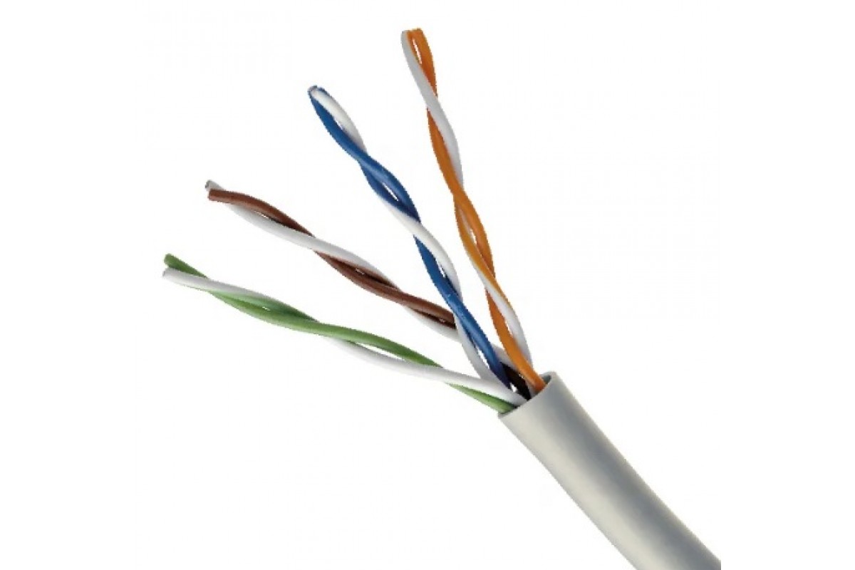
A twisted pair of wires where the signal is transmitted as the voltage difference between the two conductors. External interference induces approximately equal voltage on both wires. At the receiver, a differential amplifier subtracts one signal from the other, canceling out the common-mode noise while preserving the desired signal.
This is the principle behind Ethernet networks, professional audio (balanced connections), and many industrial protocols. The twist rate of the pair is important — tighter twists provide better noise rejection at higher frequencies.
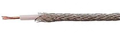
3. Shielding
The signal wire is enclosed in a conductive braid or foil — essentially a Faraday cage. This protects the inner conductor from external electric fields. The shield must be connected to the common wire (ground) to be effective.
Important considerations: the shield should ideally be grounded at only one end to prevent ground loop currents from flowing through it. In practice, the source end is usually grounded. Double-shielded cables provide even better protection but are more expensive and less flexible.
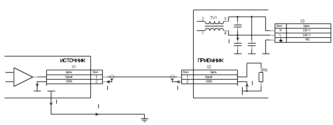
4. Galvanic Isolation
Implemented using transformers or optocouplers, galvanic isolation physically breaks the electrical connection between two circuits while still allowing signal transfer. This prevents equalizing currents from flowing between devices with different ground potentials.
Transformers can also pass power along with the signal. Audio transformers are common in professional sound equipment. Optocouplers use light to transfer signals and provide complete electrical isolation. Modern digital isolators use capacitive or magnetic coupling for high-speed applications.
Special Cases
Stereo Audio Transmission
For stereo signals, it is better to use separate shielded cables for each channel rather than running both channels as a twisted pair inside a single shield. Running two signal conductors inside one shield causes capacitive coupling between channels, leading to crosstalk. Each channel deserves its own shielded conductor with its own return path.
Digital Interfaces (RS-485, CAN, LVDS)
These use a differential pair with an optional shield. The characteristic impedance is typically 110–120 Ohms. It is essential to connect the common (ground) wires of all devices on the bus — a common mistake is to assume that differential signaling eliminates the need for a ground connection. Without it, the common-mode voltage can exceed the receiver's input range, causing communication failures.
Termination resistors matching the cable's characteristic impedance should be placed at both ends of the bus to prevent reflections.
High-Frequency Transmission (Coaxial Cables)
At radio frequencies, strict matching of characteristic impedance (50 or 75 Ohms) is critical throughout the entire signal path. Any deviation causes reflections that distort the signal. The "coaxiality" — the concentricity of the inner conductor within the outer shield — must be maintained along the entire cable length and through all connectors.
Always use connectors of the same impedance standard as the cable. Mixing 50-Ohm and 75-Ohm components creates impedance mismatches and signal degradation.
Magnetic Fields
An important caveat: shielding (Faraday cage) does not protect against magnetic fields. Only differential transmission can effectively neutralize interference from magnetic fields, because the magnetic flux induces equal and opposite voltages in the two conductors of a twisted pair, which cancel out at the differential receiver.
The practical recommendation is to keep signal cables away from sources of strong magnetic fields — transformers, motors, power cables carrying high current. When crossing power cables is unavoidable, cross them at 90 degrees to minimize coupling.
Summary of Noise Reduction Methods
- Shunting — reducing source and receiver impedances to minimize noise voltage
- Differential transmission — using twisted pairs and differential receivers to cancel common-mode noise
- Shielding — enclosing conductors in a grounded conductive shell to block electric fields
- Galvanic isolation — breaking the electrical connection between circuits using transformers or optocouplers
- Combining methods — for maximum protection, use multiple techniques together (e.g., Gigabit Ethernet uses differential pairs with shielding and transformer isolation)
Each method addresses a specific type of interference. In practice, combining several approaches yields the best results. Understanding these fundamentals allows you to diagnose noise problems and choose the most effective solution for your specific application.


