A Christmas Tree Ornament for New Year's
A maker builds a PCB snowflake ornament with 60 LEDs powered by an ATmega microcontroller and a CR1220 coin cell, complete with power optimization, epoxy resin coating, and multiple blinking modes that run for days on a tiny battery.
Greetings, Habr! Before New Year's, to get into the holiday spirit, I wanted to make something unusual and new. We all decorate the Christmas tree, put a star on top, hang ornaments on the branches, and wait for Ded Moroz (Russian Santa Claus). Zhenya, 41 years old.
As always, the idea was born spontaneously, when there was almost no time left for implementation. I'm writing this article while simultaneously working on the software, and right now I'm waiting for the PCBs to arrive from manufacturing — not even knowing if the design will work. Since this winter hasn't blessed us with snow in Saint Petersburg, I couldn't think of anything better than making a Christmas tree ornament in the shape of a snowflake.
When I was a child, I used to make garlands from old Soviet 6.3V bulbs that switched using a multivibrator circuit. Now, using a microcontroller (I'm not ready to build on discrete components), you can make something much more interesting, and the accessibility of PCB manufacturing means you don't have to use cardboard as the base for mounting components.
Schematic and Components
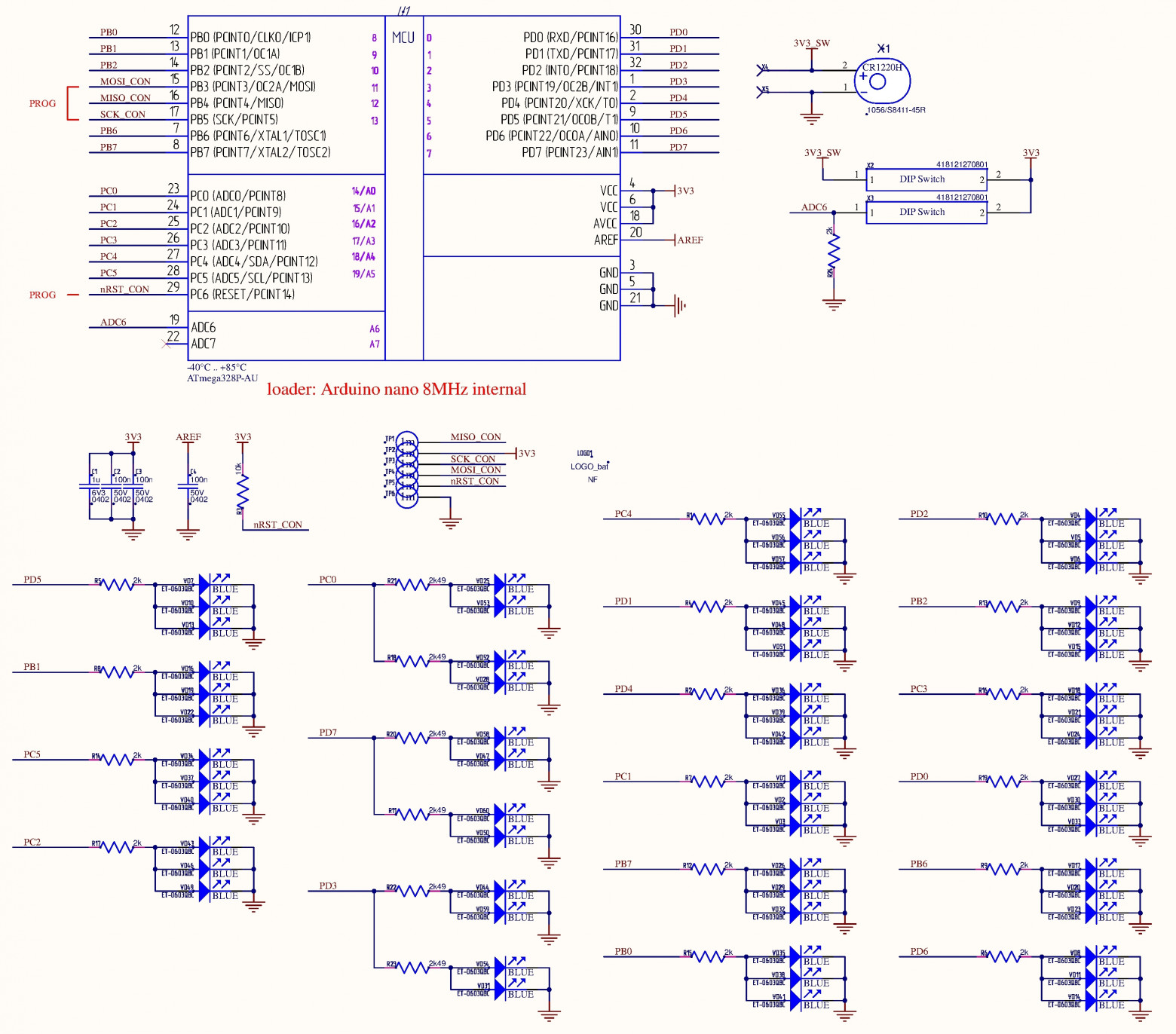
I wanted a device with a minimum of components, since a snowflake-shaped PCB won't accommodate something like shift register ICs. Although the switching would be more impressive — random lighting, for example. Since I don't want to run power wires to a Christmas tree ornament, I'll use a battery. A rechargeable battery would be more efficient, but then you'd need to design a charging circuit, and the dimensions don't allow it.
I managed to create 19 groups, each consisting of two or three LEDs. Initially I used 0603-sized resistors for each LED. When I laid everything out on the board, I realized there was no room left for routing and vias. I had to optimize.
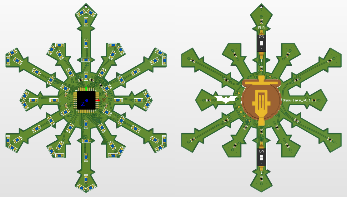
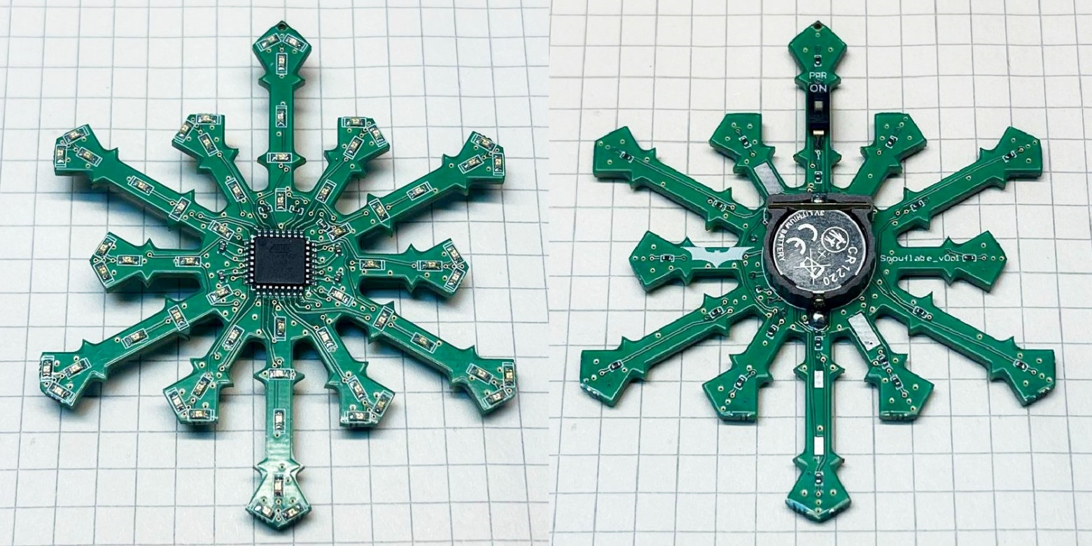
For power, I placed a battery holder for CR1220 and CR1632 (choose one) — approximately 40 mAh and 120 mAh, respectively. For this many LEDs (60 total), that's very little, but nothing bigger would fit. I stocked up on batteries for the entire New Year's holiday season.
For disconnecting the battery and switching operating modes, I placed a pair of single-position DIP switches. Only they fit across the width of the snowflake's rays.
This is when I realized I didn't need the 0603 resistors or the crystal oscillator. The battery holder for CR1220 barely fit. If you make the center circle diameter larger, the ornament starts looking less like a snowflake.
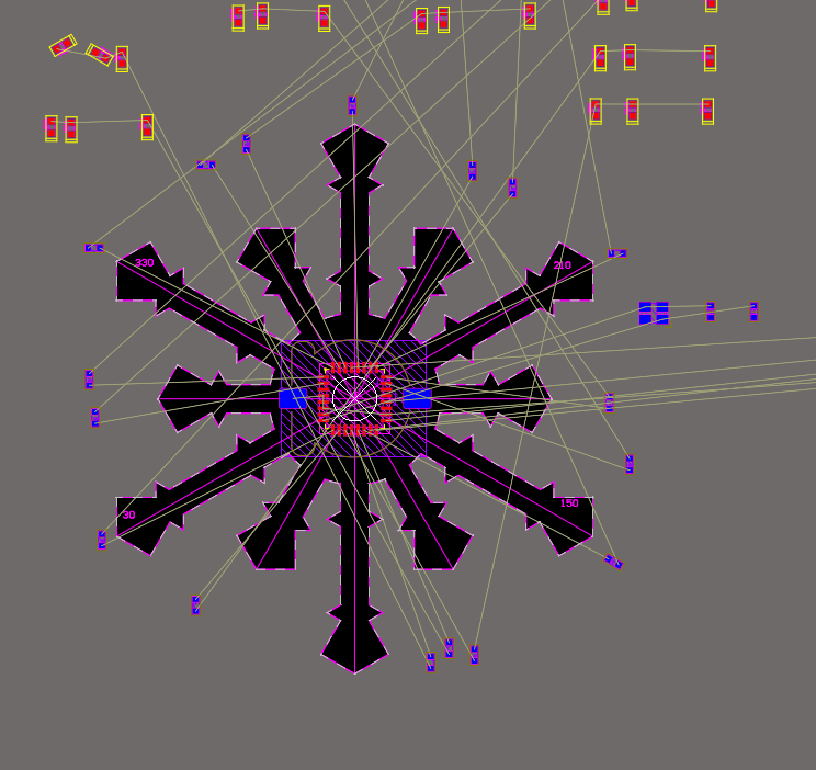
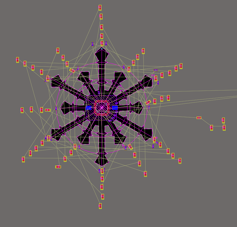
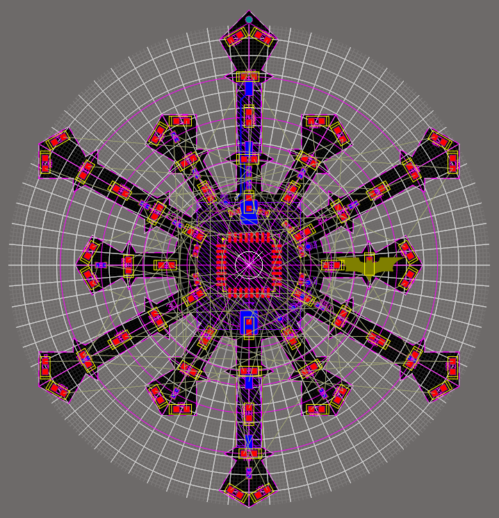
PCB Design
It was only when I started writing the software that I noticed I had slightly messed up the LED distribution, but I think it's not critical.
Unfortunately, Altium Designer doesn't support routing at 30-degree angles, so I had to get creative using "PolarGrid" and do the routing with alignment to that grid.
At first it seemed like this would be impossible to route, since the rays are relatively thin. I had to redistribute the LEDs several times. I ran the automatic router, but after 10 minutes Altium reported that it was impossible. Fine, I'll do it myself.
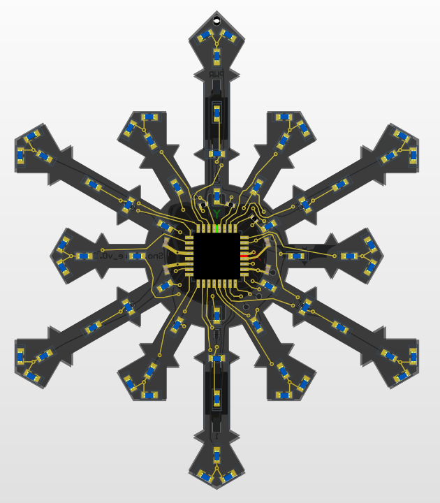
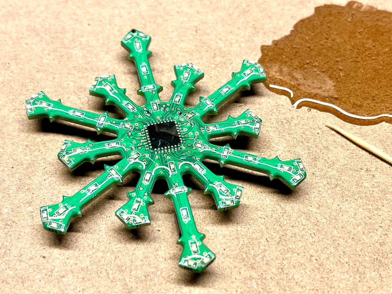
Overall it turned out quite decent. The only question is how it will look on the tree. Yes, the total height of the snowflake is 70 mm. I even drilled a hole at the top for a thread to hang it from a branch.
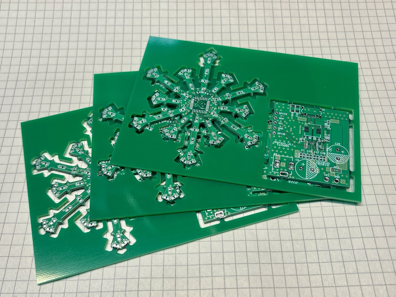
Because of the battery, it looks bulky, but there's no other way. Right at this moment the courier delivered the still-warm PCBs.
Actually, I needed to test the MPQ4242BGVE Power Delivery chip, and I ordered the boards specifically for that. Hence the rush, the juggling of projects, and the green solder mask (white would have looked better, but traces aren't always visible underneath it).
The board on the monitor, I'll tell you, looks much larger than it actually is. I think it turned out pretty well.
Assembly and Testing
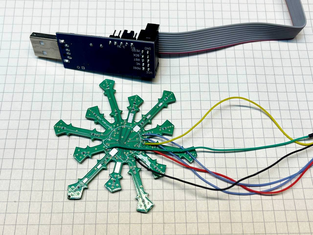
For programming I provided test points, and I regretted not placing a temporary connector under the battery for programming and debugging. For pairs of LEDs I used 2k47 resistors, for groups of three — 2k0. Current consumption with all LEDs lit simultaneously (ET-0603QBC) is about 9 mA, which pleased me.
I only had trouble with GPIO PB6 and PB7, which in Arduino Nano are used for the crystal oscillator. I assumed that after programming the fuses for internal oscillator operation, I could immediately use those pins as I/O (nope).
For switching between the two blinking modes, I decided to use a button that you hold down when turning on the device. In setup() I read the ADC value and decide which algorithm to use based on that. You could also add EEPROM memory storage for the mode.
I swapped in the holder for a CR1632 battery to measure the maximum runtime. The device ran for two hours, then clearly rebooted from insufficient power, but continued working for another 30 minutes. I didn't check further. Time to start optimizing power consumption.
Power Optimization
First, I check what the consumption will be if we sleep between cycles. I use this function:
LowPower.powerDown(SLEEP_8S, ADC_OFF, BOD_OFF);Power consumption test results (3V supply):
- All LEDs constantly on: 9 mA
- All LEDs constantly on, then SLEEP_8S: 6 mA
- LEDs off + SLEEP_8S: 0.005 mA
Excellent! For implementing sleep between LED activations, ten constants are available ranging from 15 ms to eight seconds. I'll need timeouts of 30 ms and 500 ms. Since GPIO states remain at their set values, instead of delay(30) and delay(500) consuming 9 mA, I'll sleep and spend only microamps.
In setup() I add a clock prescaler to reduce the operating frequency to 64 kHz (previously it was running at 8 MHz):
clock_prescale_set(clock_div_256);Now consumption with all LEDs lit is 6.5 mA (in SLEEP mode it hasn't changed, of course). Don't forget that at frequencies below 1.5 MHz, programming must be done in SLOW mode (reduced SPI frequency). If you do forget, you'll have to, like me, dig through the trash to find the controller that suddenly stopped programming. I use a trusty old USBasp clone — I soldered on the jumper since it was missing.
Now let's disable Brown-out Detection — the monitoring of minimum supply voltage for the microcontroller. The default value was "101" in fuses, meaning a hardware reset at voltages below 2.7V. We remove it by changing the fuses to "111" in the boards.txt file:
dior.bootloader.extended_fuses=0xFF #BOD offThis way we achieve that the LEDs continue blinking perfectly at 2.4V. You can go even lower, but visibility suffers. Ah, I wish I had added something like TPS60242 (a Capacitor Buck-Boost with output up to 25 mA) to drain the battery even further (down to 1.8V). Maybe for the next holiday...
Operating Modes
I made a couple of GIFs showing the modes. They don't look great after conversion (the speed is off), but you can get the idea. The first mode is the default.
Mode 1 — the default LED animation pattern
Mode 2 — alternative blinking pattern
Finishing Touches
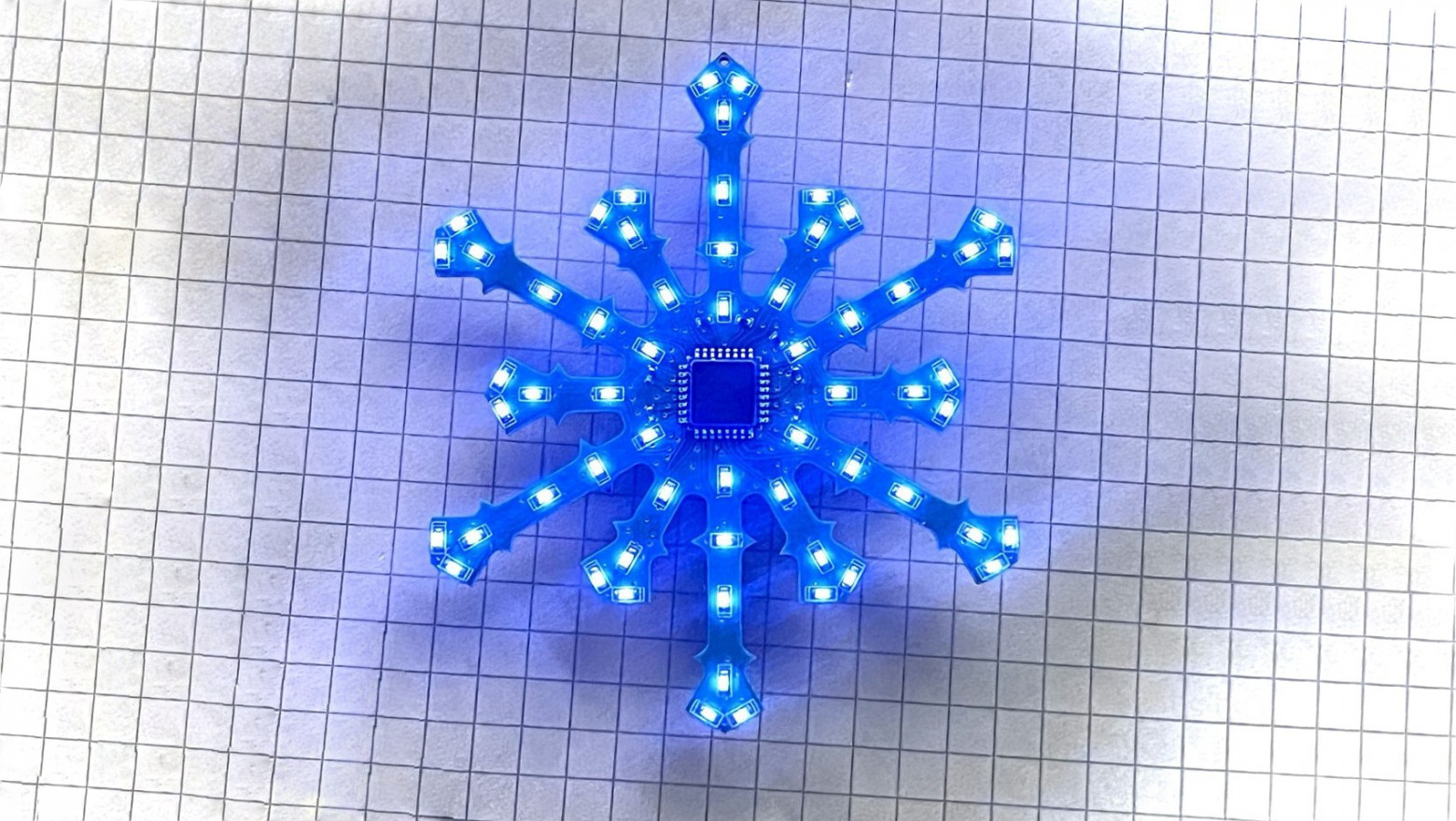
To strengthen the entire structure and give it a more aesthetic appearance, I decided to coat it with a thick layer of epoxy resin. Now it looks like it's made of glass.
Here's how it turned out. This is exactly the effect I was hoping for — now the rays look much better.
Mode 1 after the epoxy resin coating
Results
I waited at work for the batteries to die. Took it home with me. Monitored with one eye all night... the second night... the third night...
Running on a CR1220 battery in Mode 1: as of now, it has been running for three days. Brightness has visually dropped by 20–30%.
Running on a CR1632 battery in Mode 1: running for three days with no change in brightness. (UPDATE) After four days of operation, brightness loss is 20–30%. I thought it would last longer.
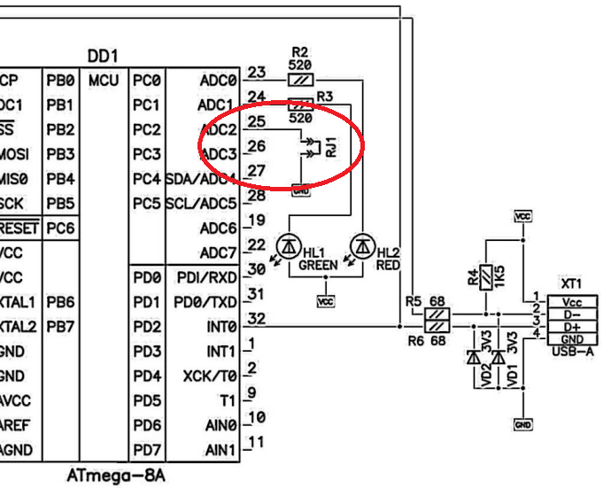
P.S. Link to the Altium source files (added a resistor to GND for the ADC): Snowflake_v0.1 on Dropbox.
P.P.S. You could add a photodiode to the board and turn on the power when it's dark.
Happy New Year! Thanks for reading, and best of luck!


