A Nixie Tube Display for a Time Machine, or How I Ended Up in the Credits of a Japanese Drama
A hobbyist develops a Nixie tube driver module called Nixierator for his CD player project, and unexpectedly gets it featured as a time machine prop in a Japanese TV drama series.
For decades now, gas-discharge digital indicators have been experiencing a renaissance. Some people build clocks and weather stations using the widely available IN-12 tubes, while others dive deep into the topic and try to set up their own production of tubes in previously unimaginable shapes and sizes.
I, on the other hand, preferred to use VFD (Vacuum Fluorescent Displays) in my projects — they require much lower supply voltages and are far more commonly available as ready-made modules that just need 5 volts of power and data.
Most Nixie tube projects I'd come across in the "beginner" category used long-discontinued decoder chips like the K155ID1 or SN74141. Many of the circuits I'd seen also economized on the number of decoders by using a single decoder for all tubes at once, multiplexing the anodes through optocouplers.
But I wanted to put two IN-12 tubes that had been sitting in a drawer for a decade into my CD player project — to display the track number or radio station. So I wanted a module similar to any other display — not much larger than the tubes themselves, connecting via a standard bus, not requiring the microcontroller to deal with dynamic multiplexing refresh and all that, and built from actively manufactured components to boot.
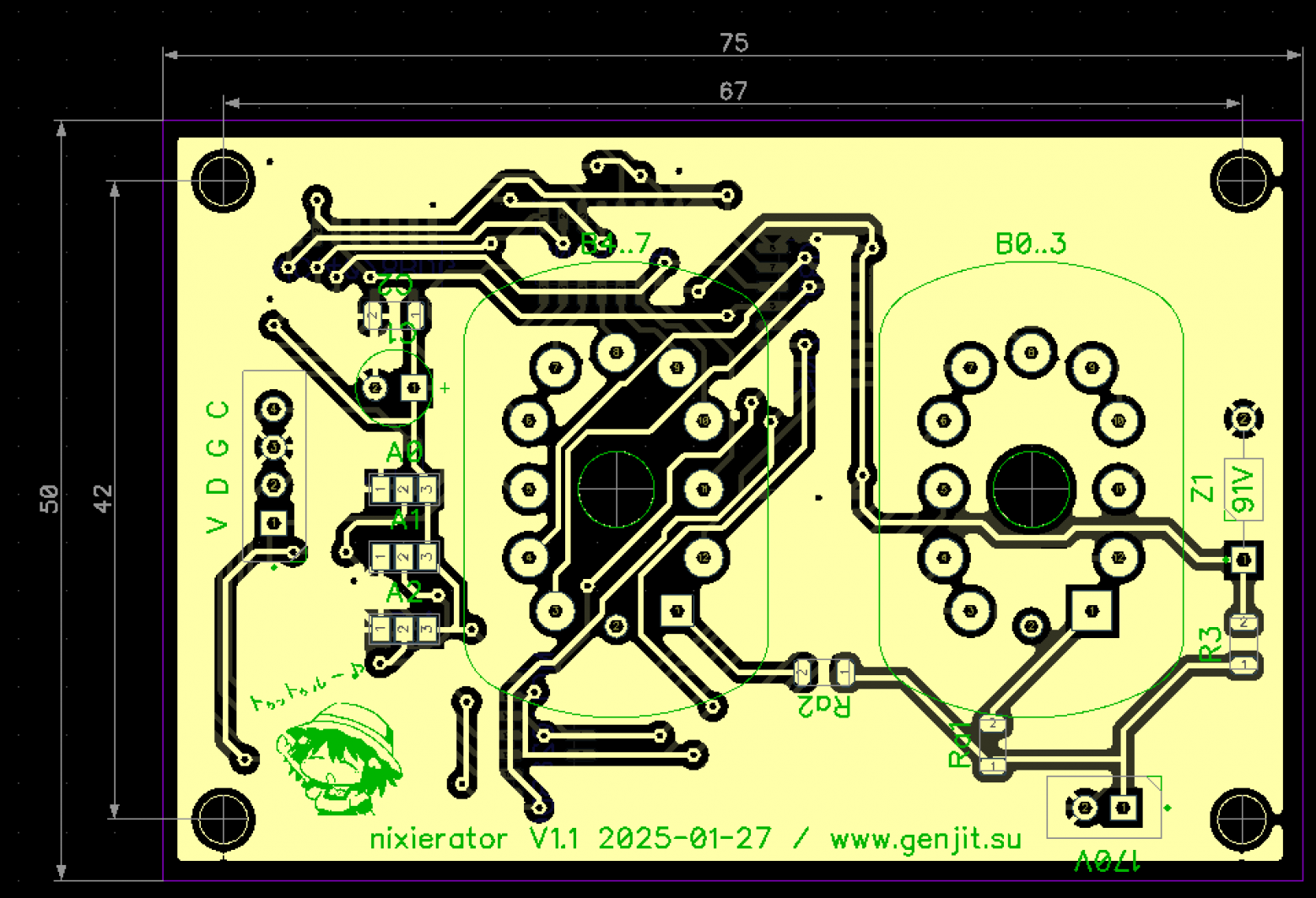
And so a side file was born in the project — a PCB with the telling name Nixierator.
How It Works
The circuit is actually quite simple for someone more or less versed in electronics. However, it might not be immediately clear to a beginner, so let's break down what it does step by step.
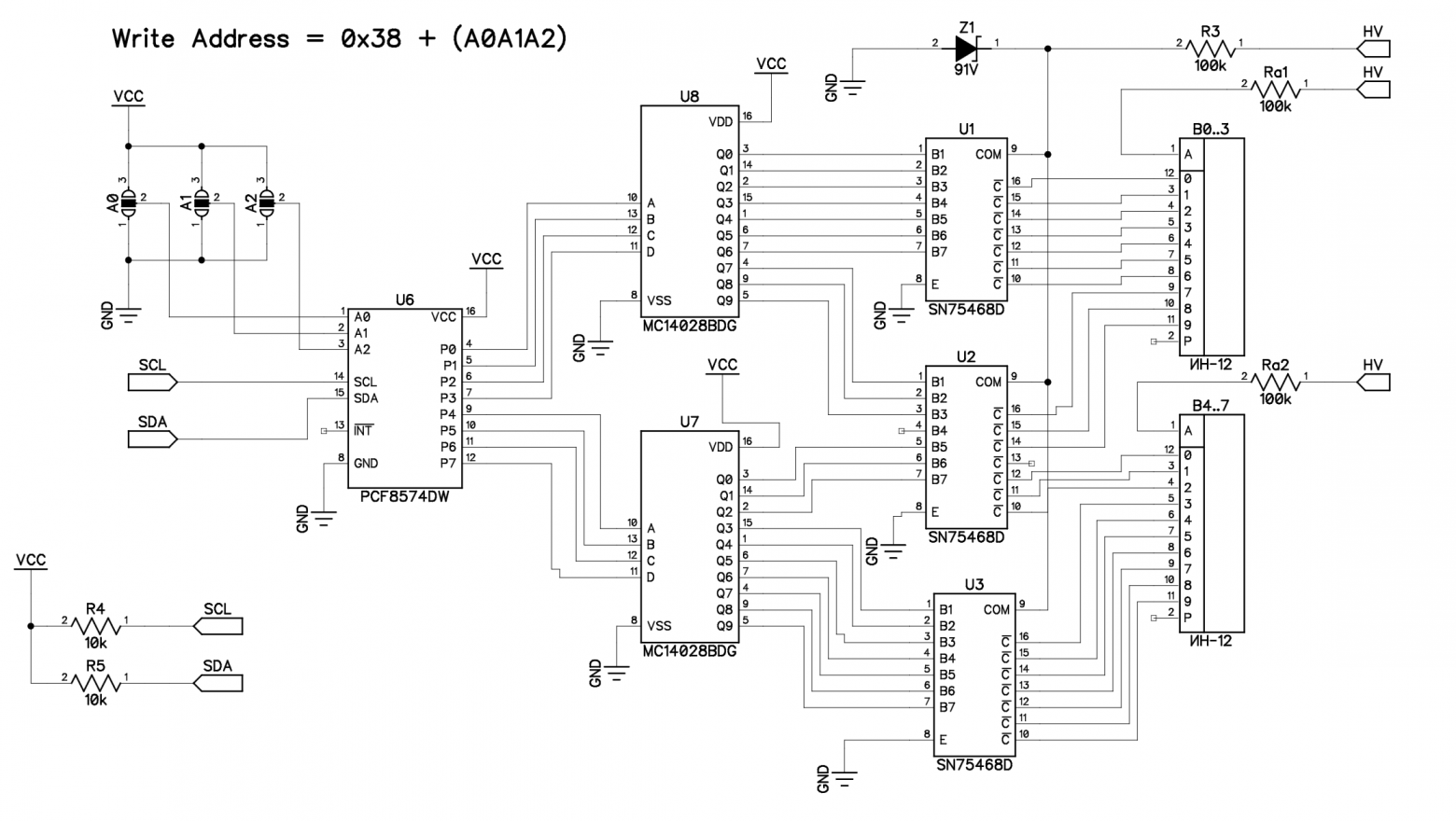
On the right you can see the high voltage input (HV) — typically 200V DC for IN-12 tubes. Resistors Ra1 and Ra2 set the current through the indicators — for IN-12, the recommended operating current is in the range of 2 to 3.5 mA, and 100 kOhm at 200 volts provides a gentle operating mode at the lower end of this range.
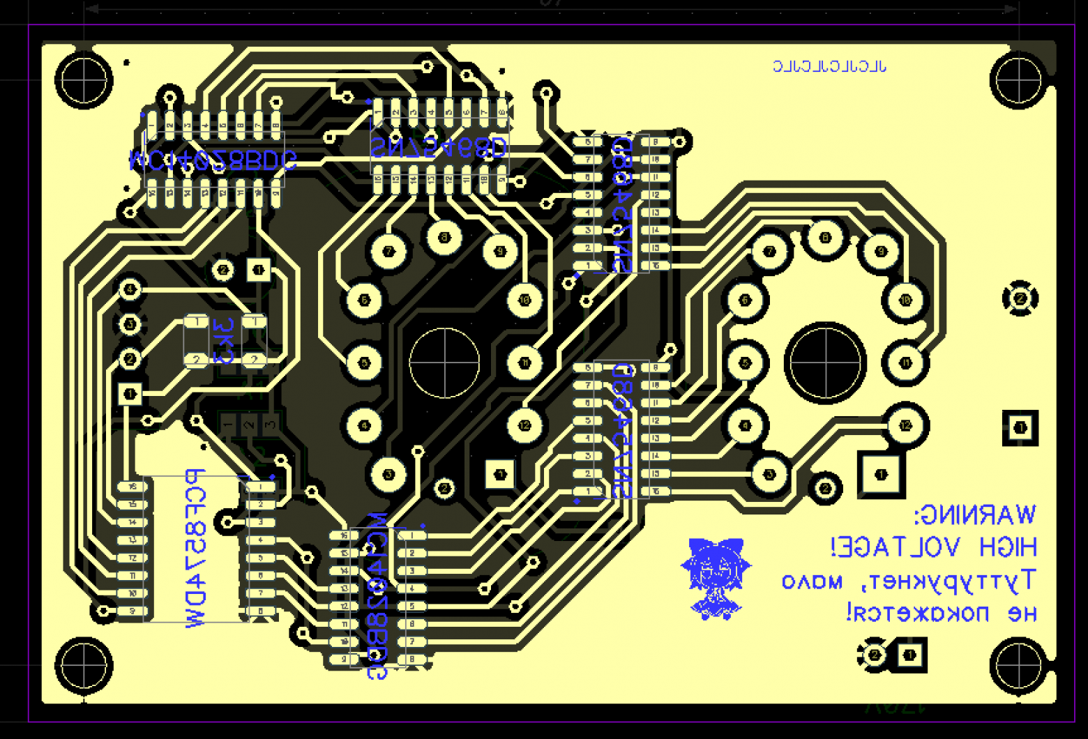
On the left is the data input from an Arduino — the familiar I2C bus. R4 and R5 pull it up to the positive supply voltage, in case pull-ups aren't installed on the circuit that will be controlling the module. Data travels through it to the 8-bit register PCF8574, whose address is set by jumpers A2, A1, and A0.
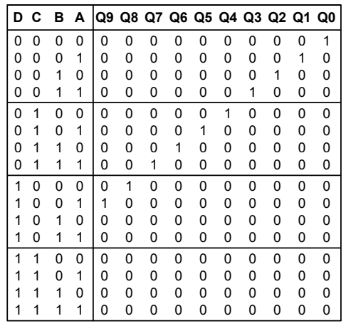
The 8-bit output from the register is split into nibbles feeding two MC14028 decoders. Each decoder has a 4-bit input and 10 outputs. If the binary value on the input falls within the decimal range of 0 to 9, the corresponding output from Q0-Q9 goes high; otherwise, all outputs remain low.
So, for example, if we write the hexadecimal number 0x28 to the PCF8574 register — the first (high) 4 bits go to the upper decoder (U8) and activate its output number 2, while the second (low) 4 bits go to the lower decoder (U7) and activate its output number 8.
Then all these outputs go through the SN75468 chip — an array of seven Darlington transistors. These transistors give us voltage amplification, so we can switch the power to the desired cathodes of the gas-discharge tubes using logic-level signals (0–5V). When a decoder output is active (logic 1), the corresponding transistor in the array opens and connects its cathode to ground, lighting it up. If the decoder output is inactive (logic 0), the transistor is off — no current flows through the cathode, and it doesn't glow.
The attentive reader will notice that the SN75468 datasheet specifies a maximum collector-emitter voltage of 100 volts. But our tubes run on 200 volts! How does this work, and why don't the closed transistors get destroyed by the high voltage?
This is exactly why the circuit has a 91-volt Zener diode Z1. It's connected between the common collector point of all transistors inside the SN75468 and their common emitter. Thus, the transistors will never have more than 91 volts between collector and emitter — either 0V (transistor open, cathode lit) or 91V (transistor closed, cathode off).
Resistor R3 sets the Zener current to achieve its proper operating mode and ensure the correct voltage at the point between Z1 and R3. You can find circuits online where this resistor is omitted, hoping that the parasitic current inside the unlit tube from anode to cathodes will be sufficient on its own. But then the voltage at the point between Z1 and R3 could end up below 91 volts — depending on the particular tubes and Zener — while the voltage drop across the tubes actually increases, and even the "off" cathodes glow partially or fully. Ideally, R3 should be selected according to the Zener datasheet so the current through it is optimal, but I just threw in 100 kOhm to avoid ordering extra values, and everything worked perfectly.
Why Does This Work?
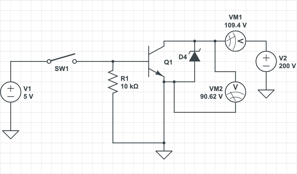
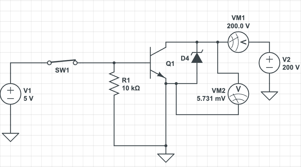
As we've already established, in our circuit the lit cathode has a potential of 0 volts, and the unlit one has 91 volts. However, the digits will turn off despite the unlit cathodes' potential being lower than the anode potential.
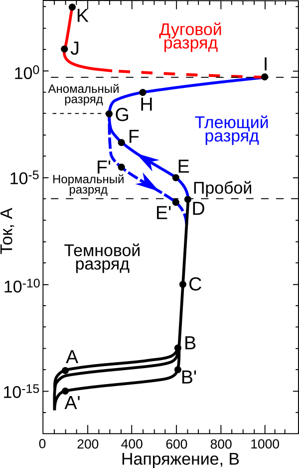
The thing is that the volt-ampere characteristic of a gas-discharge indicator is nonlinear, similar to that of, say, an LED.
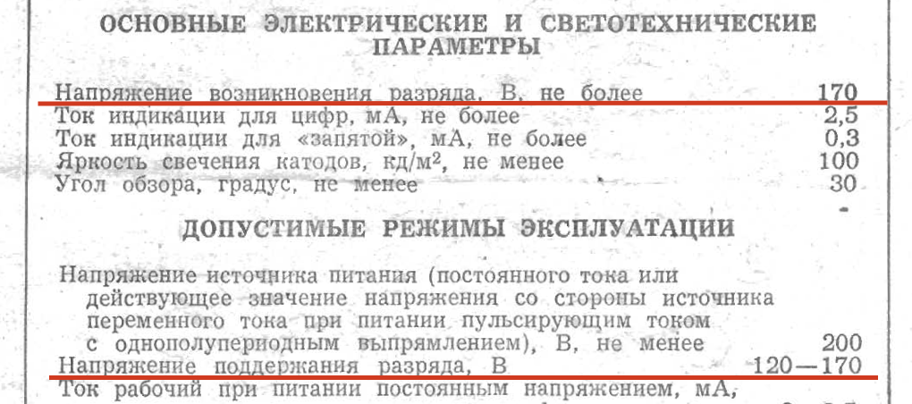
The voltage at which current begins to flow is called the striking voltage (point D on the graph) — at this voltage, a glow discharge occurs in the gas medium, which glows around the cathode.
After this, there's enough heated and ionized gas in the tube for the glow discharge to sustain itself even as voltage decreases. However, below a certain voltage, it can no longer sustain itself and extinguishes — this is called the maintaining voltage (point E' on the graph).
In the context of our circuit, the voltages are:
- When a digit is active: cathode potential is 0V (transistor is open to ground), anode potential is 200V, potential difference (voltage) is 200V, which is above the striking voltage of 170V. Accordingly, the cathode lights up.
- When a digit is off: cathode potential is 97V (transistor is closed, voltage set by Zener), anode potential is 200V, resulting voltage is (200 - 97) = 103V, which is below the maintaining voltage of 120V. Therefore, the cathode extinguishes, although some minuscule current continues to flow through it.
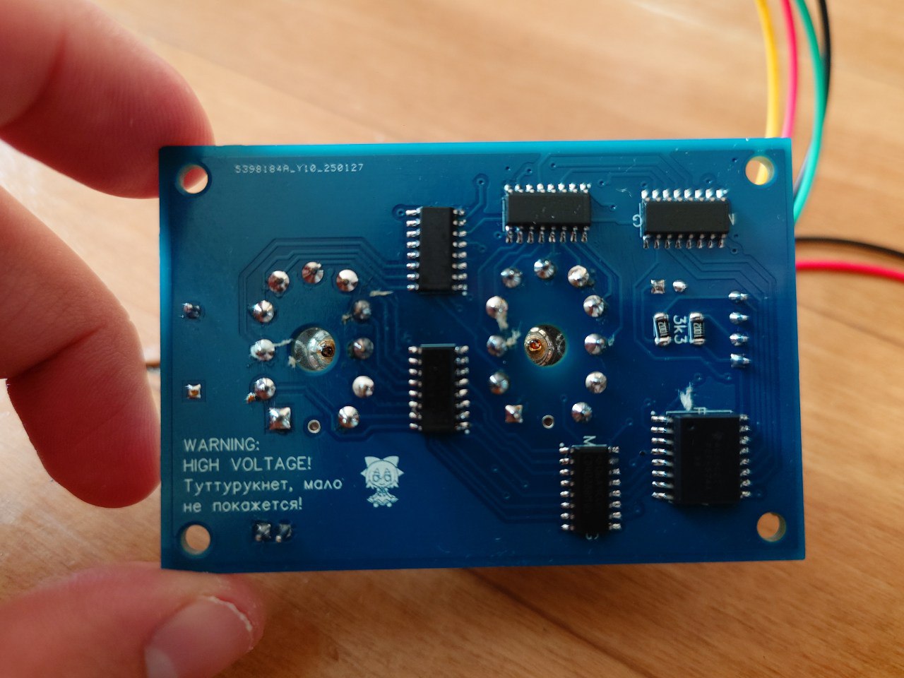
Printed Circuit Boards
I quickly laid out the board in DipTrace — keeping the high voltage and logic traces as far apart as possible. It probably wouldn't arc over, but it's scary to have such things close together.
In future revisions, if there are any, I'd like to add through-hole connectors for power and data. But since I ended up not using even this one, when that'll happen is anyone's guess :-)
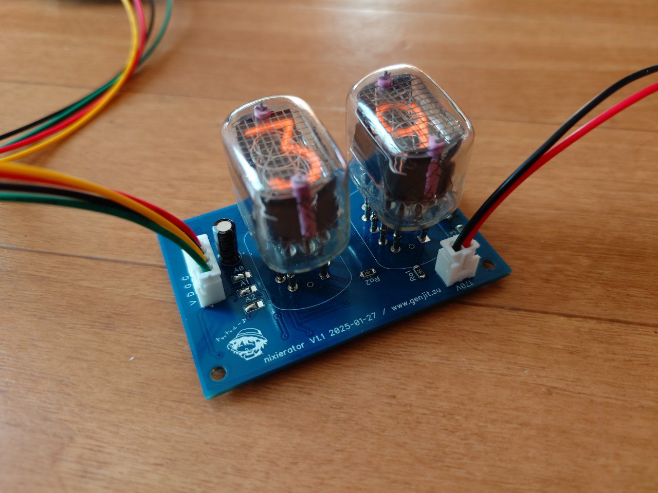
I didn't bother with the high-voltage supply for now and used a ready-made boost converter module from AliExpress. Ideally, that should be integrated onto the board too, but not this time.
Assemble, connect. It works, hooray!
Code
By default, all PCF8574 pins work as outputs, so to work with it through Arduino, you don't need any library other than the standard Wire. Here's example code that counts seconds from 0 to 99 on one such module and blinks the zero in the high digit on odd values less than ten:
int address = 0x38; // address set by jumpers

// Displays a two-digit number on the Nixie indicator
// @param num Number in range 0-99
// @param leading_zero Enables or disables 0 in the high digit if the number is less than 10
void nixieShow(int num, bool leading_zero) {
    if(num >= 100) num = (num % 100);
    int bcd = (num % 10) | ((num / 10) << 4); // Convert number to BCD

    if(!leading_zero && (num / 10) == 0) {
        // Disable first digit if leading zero is not needed
        bcd |= 0xF0;
    }

    Wire.beginTransmission(address);
    Wire.write(bcd);
    if(Wire.endTransmission() != 0) Serial.println("send error!!");
}

void setup() {
    Serial.begin(115200);
    Wire.begin();
}

int second = 0;
void loop() {
    if(second == 99) second = 0;
    else second++;
    nixieShow(second, (second % 2) == 0);
    delay(1000);
}
The only nuance here is converting the number to binary-coded decimal — so that when displaying the decimal number 39, the register receives binary 0011 1001b == 0x39 == 57d, not 0010 0111 == 0x27 == 39d.
A Moment of Fame from an Unexpected Source
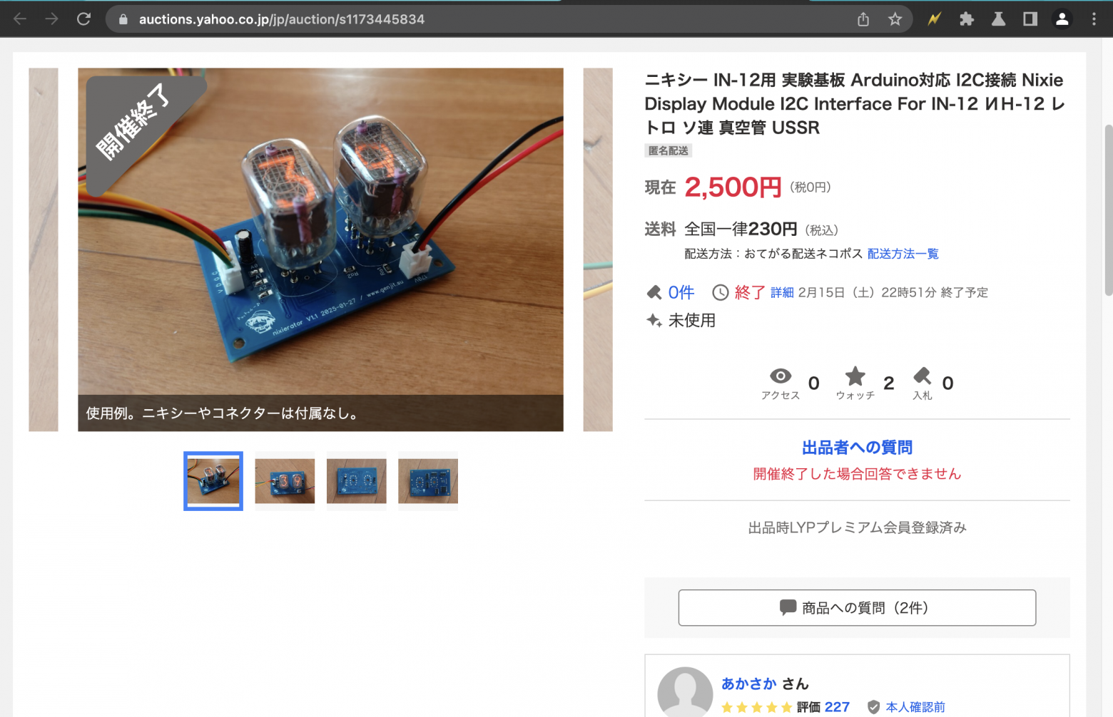
So I ordered the boards and built them, but I only needed one for the player, and the minimum order from JLC PCB is four boards. Throwing away the extras would be wasteful, and putting them in a drawer — who knows when they'd be needed.
So I ordered parts for all five boards (except the tubes) and listed the extra four on Yahoo Auctions — the local equivalent of the now-defunct auction sites. Specifically for beginner Arduino enthusiasts like myself who'd love to play with Nixie tubes but don't know where to start.
A couple of days later, someone showed up in the comments asking: can you chain several of these modules together? Can you display something other than the current time or weather? And at the end, they asked me to write to them directly via email.
It turned out they needed a display panel for a time machine prop in a TV drama! Exactly 8 digits — from my last four remaining boards.
The drama turned out to be a screen adaptation of the board game "Hachigatsu no Time Machine" (August Time Machine), in the science fiction genre. Apparently, the cliche of displays based on 1950s technology is here to stay in this part of the world :-)
As it turned out, among the vast variety of Nixie clocks available on Yahoo Auctions, most are either assembled from ready-made Chinese kits by beginner hobbyists, or at best, designed around pre-made firmware. Nobody was willing to dig into the firmware to turn a clock into a plain display.
On top of that, test footage showed that with dynamic multiplexing — when digits light up very quickly one after another — almost any change in shutter speed caused the digits to flicker, like filming a CRT monitor, which is unacceptable for cinema.
And then, by pure luck, I list my boards for sale! The circuit described here implements static driving — all digits are always lit simultaneously, so no flickering occurs.
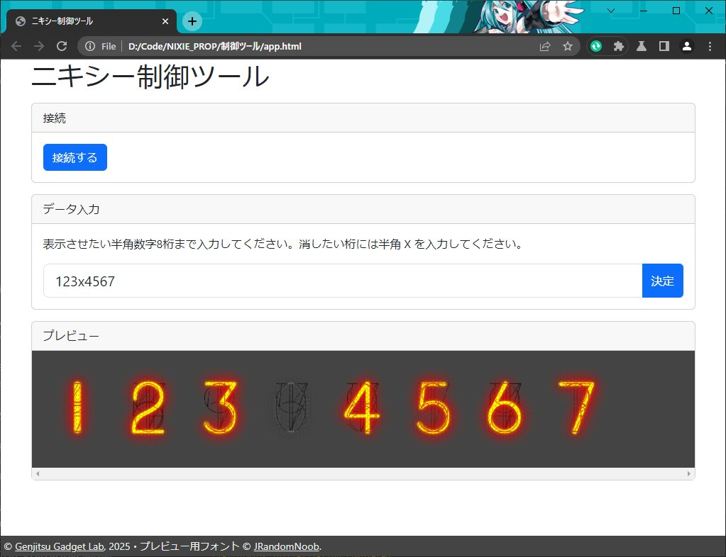
Initially, the idea was to simply load digits into memory via USB-UART and a simple single-page web app communicating with the device through WebSerial.
However, it later occurred to me that dragging a laptop around the studio for every little thing wasn't the best idea, and the micro-USB connector on the Arduino Nano is quite fragile. Replacing the Arduino with an ESP8266 also seemed suboptimal — again you'd need a computer or phone, plus on a film set the radio spectrum is typically saturated, and the ESP has historically had mediocre radio performance. And the enclosure for this part of the time machine was supposed to be steel — meaning an external antenna would be needed, and I'd run out of ESPs with IPEX connectors...
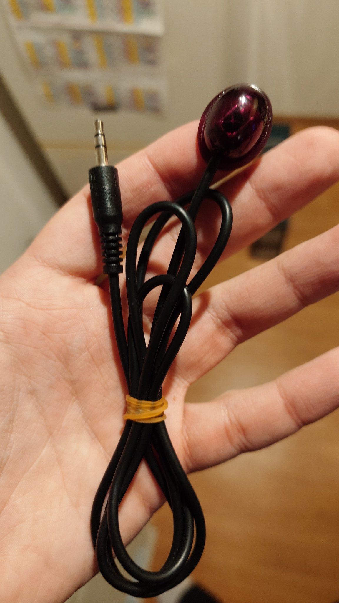
Then my eyes fell on an infrared receiver tail from a TV tuner sitting in the parts box.
That's exactly what's needed! It can be stuck somewhere inconspicuous on the set, and if the built-in cable isn't long enough, you can always buy a headphone extension cable at the nearest store (if there isn't one on set already) and extend it without much hassle.
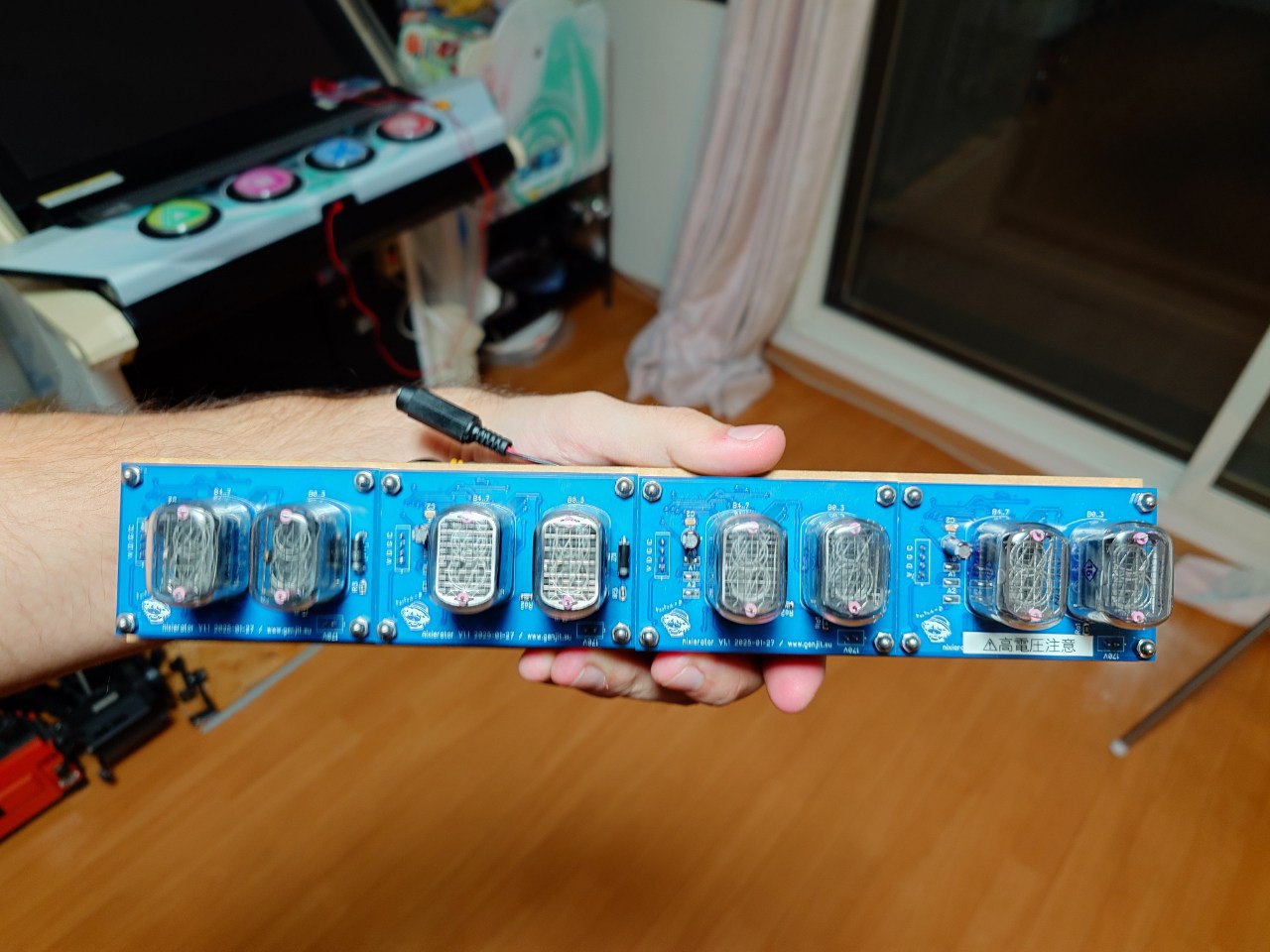
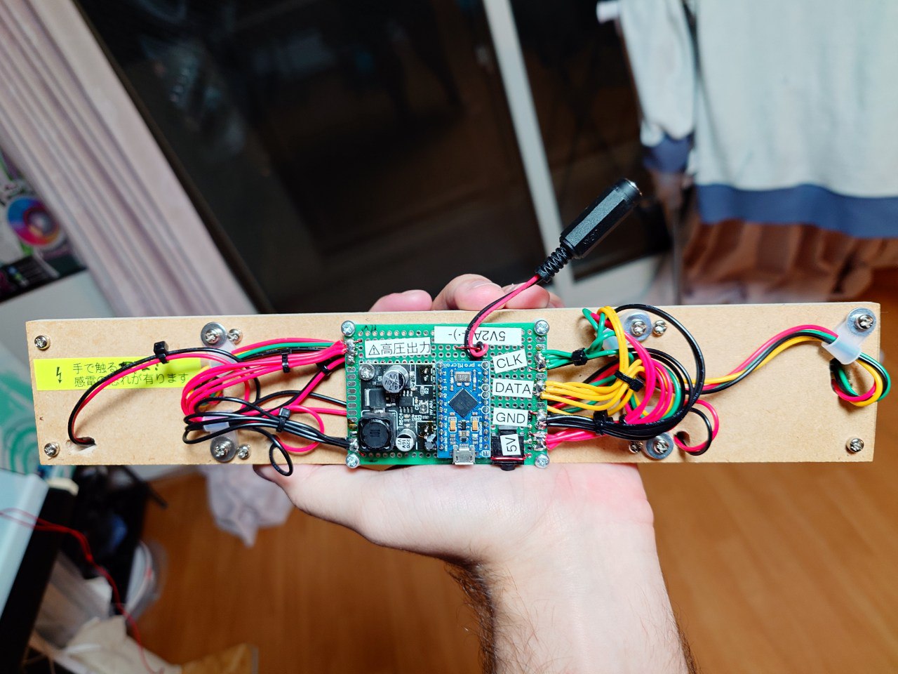
In the end, additional tubes were purchased and from available parts a genuine time machine display was assembled.

For control, a remote of unknown origin with a D-pad and power button was extracted from the same junk box — just enough buttons for all the needed functions. Everything had to be packed in quite tightly, so the control scheme ended up being non-trivial:
| Mode → | Off | On | Editing | |
|---|---|---|---|---|
| Button ↓ | Press | Press | Hold | Press |
| Power | Show last active number | Turn off screen | Edit current memory slot | Save current number to edited slot |
| 1 / Up | Show number in slot 1 | Increment digit under cursor | ||
| 2 / Left | Show number in slot 2 | Cursor left | ||
| 3 / Right | Show number in slot 3 | Cursor right | ||
| 4 / Down | Show number in slot 4 | Decrement digit under cursor | ||
After approval from the prop masters and director, the display was sent to the Azuma Kobo workshop, where the main prop was being built. A couple of months later, the time machine finally saw the light of day.
Part of the display even made it onto the show's poster.
And the digit-scrolling effect made it into the opening credits.
The show began airing on May 4, 2025 on the BS12 channel.
This project made me think about some decidedly non-technical things.
Life is unpredictable — you never know what will take off. A ton of effort went into the CD player, but unexpectedly, the side developments that didn't even make it into the player also proved worthwhile. And really, who'd have thought — hobby electronics for fun, and big-time show business — yet here we are.
Second, maybe I should try pivoting from the already tiresome world of programming into something like this. The money might be less, but there's incomparably more creativity and interest.
And third, you can always read the series about my life on Telegram :-)
Links
- Schematics and PCBs on GitHub
- Using the SN75468 as a Nixie Tube Driver — lucsmall.com
- Azuma Kobo — the team that built the time machine prop itself
- Show page on the BS12 channel website


