Tetrode, Pentode: Why Does a Triode Need Additional Grids?
A technical history of vacuum tube evolution — from the simple diode through the triode to the tetrode, pentode, and beam tube — explaining why each additional grid was necessary.
The history of electronics is a story of solving problems that create new problems. Nowhere is this more evident than in the evolution of vacuum tubes, where each innovation addressed a specific engineering limitation only to reveal another one lurking beneath.
The Vacuum Diode: Where It All Began
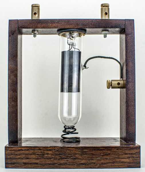
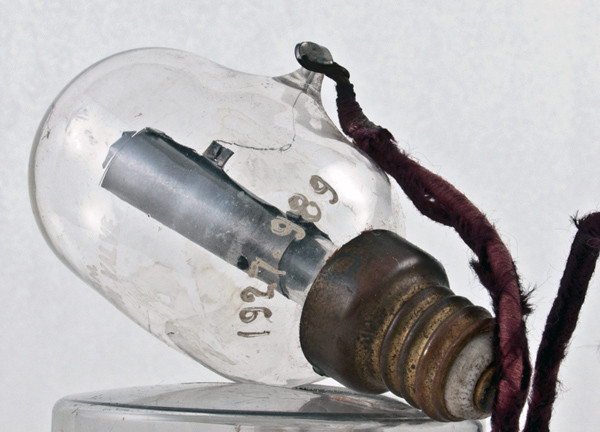
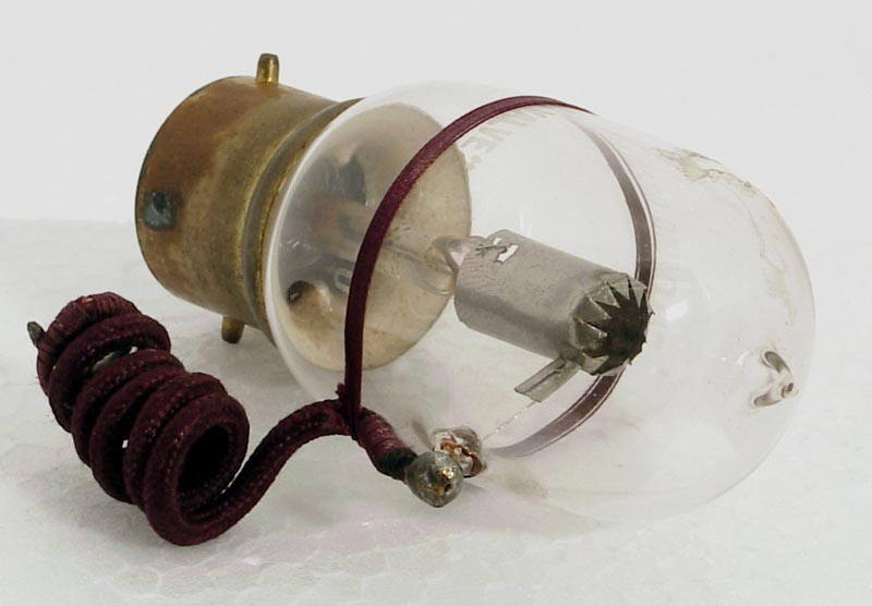
The story begins with thermionic emission. When a metal is heated, some of its free electrons gain enough energy to escape the surface. Place this heated element (the cathode) inside an evacuated glass envelope together with a second electrode (the anode), apply a positive voltage to the anode, and the freed electrons will flow toward it — creating an electric current.
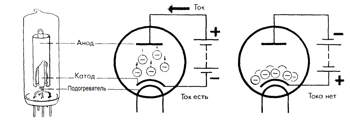
This is the vacuum diode — the simplest electronic tube. Current flows in only one direction: from cathode to anode. Reverse the voltage, and no current flows, because the cold anode doesn't emit electrons. This property made the diode useful as a rectifier, converting alternating current to direct current.
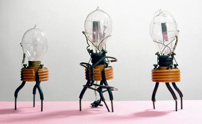
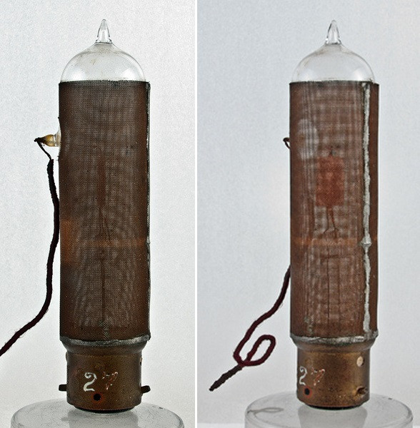
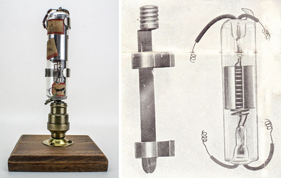
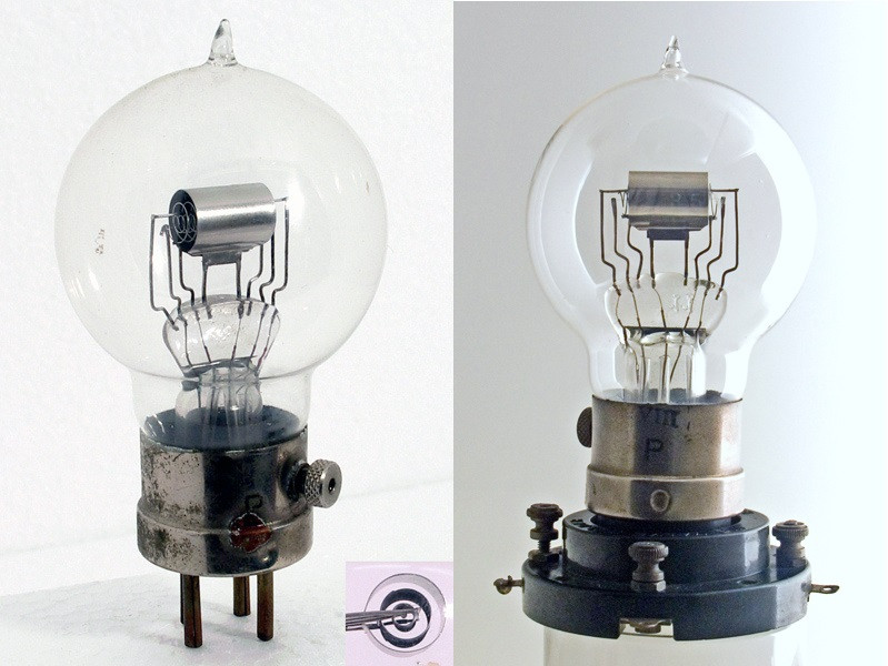
John Ambrose Fleming built the first practical vacuum diode in 1904 for use as a radio wave detector. It was a landmark invention, but it could only detect signals — not amplify them.
The Triode: Adding Control
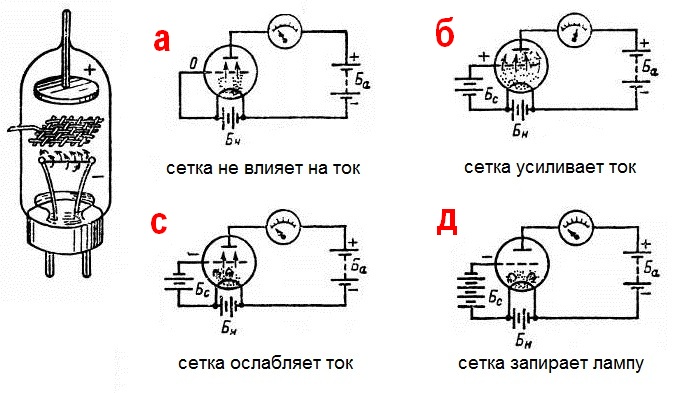
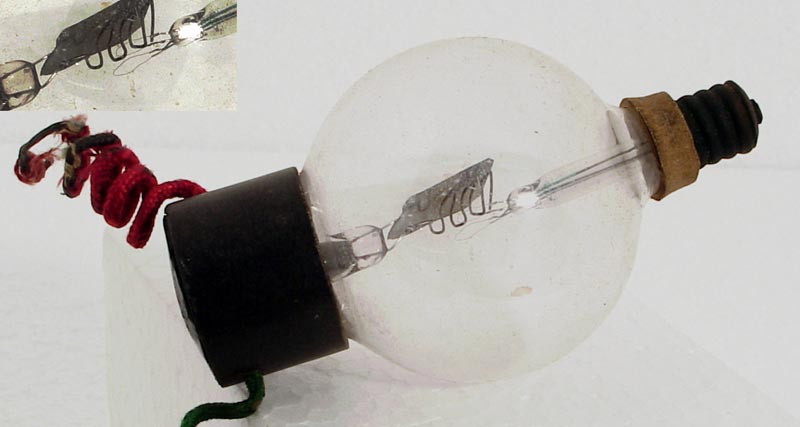
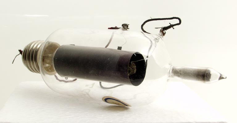
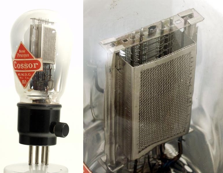
In 1906, Lee de Forest added a third element — a wire mesh grid placed between the cathode and anode. This seemingly simple modification created the triode, and with it, the entire field of electronics as we know it.
The control grid's voltage influences the electron flow. A small negative voltage on the grid repels electrons and reduces the current; a less negative voltage allows more electrons through. Crucially, a small change in grid voltage produces a large change in anode current — this is amplification.
Here's a fascinating historical irony: de Forest invented the triode primarily to circumvent Fleming's diode patent, not to create an amplifier. The amplifying properties of his "Audion" weren't recognized for another six years, until other engineers realized what the device could actually do.
The triode revolutionized telecommunications. It made long-distance telephone calls possible, enabled radio broadcasting, and launched the entire field of electronic amplification. But as engineers pushed the triode to higher frequencies, they hit a wall.
The Triode's High-Frequency Problem
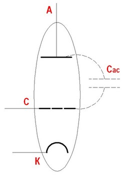
The fundamental issue was parasitic capacitance between the control grid and the anode. These two electrodes, sitting close together inside the tube, form a tiny capacitor — typically in the picofarad range. At low frequencies, this capacitance is negligible. But at higher frequencies, it creates a feedback path from the output (anode) back to the input (grid).
This feedback causes two serious problems. First, it reduces the effective gain of the amplifier. Second, and worse, it can cause the amplifier to self-oscillate — turning your carefully designed amplifier into an unintended oscillator. Engineers used neutralization circuits to compensate, but these were finicky, frequency-specific, and added complexity.
The Tetrode: A Second Grid
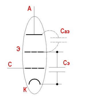
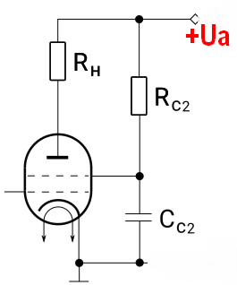
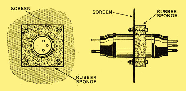
The solution came in 1919, when Walter Schottky proposed adding a second grid — the screen grid — between the control grid and the anode. This screen grid was connected to a positive voltage and acted as an electrostatic shield, reducing the grid-to-anode capacitance by a factor of hundreds or even thousands.
The four-electrode tube — the tetrode — was a major improvement. It could amplify at much higher frequencies without the self-oscillation problems that plagued triodes. Radio receivers became more practical and more sensitive.
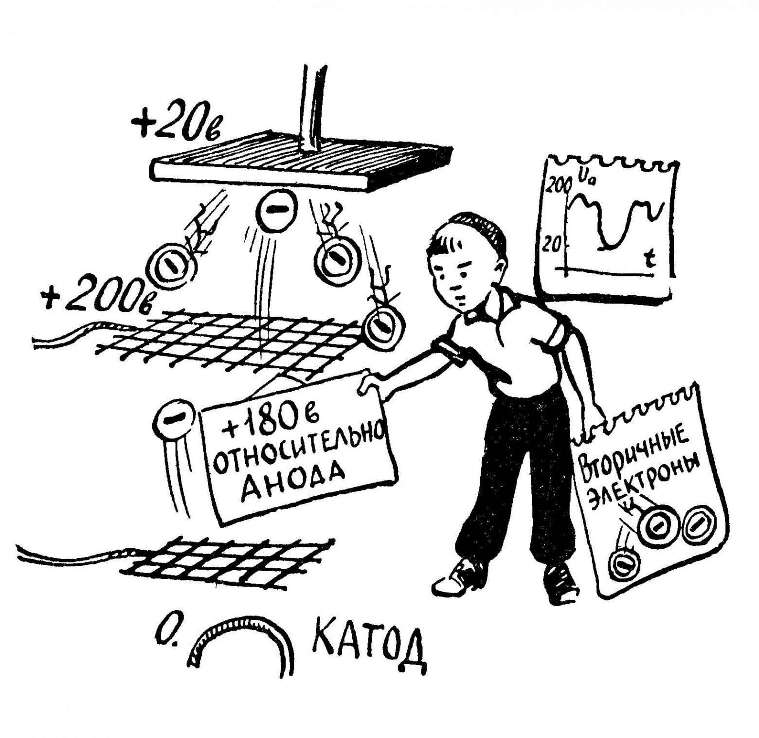
But the tetrode introduced its own problem: the dynatron effect. When electrons strike the anode at high velocity, they can knock loose secondary electrons from the anode's surface. Normally, the anode's positive voltage pulls these secondary electrons right back. However, in a tetrode, the screen grid is also at a positive voltage. If the anode voltage momentarily drops below the screen grid voltage (which happens during large signal swings), the secondary electrons are attracted to the screen grid instead of returning to the anode.
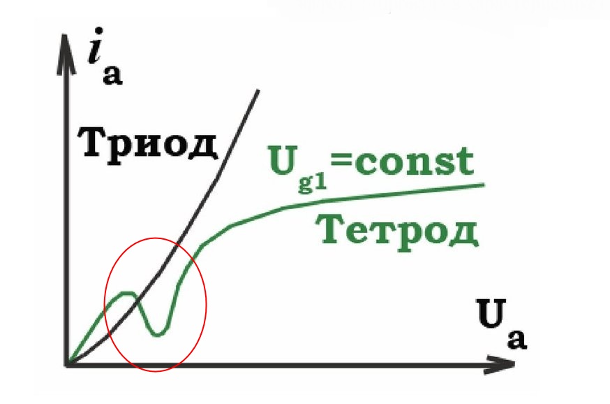
This creates a region of negative resistance in the tetrode's characteristic curve — a kink where increasing anode voltage actually decreases anode current. This distorted the signal and limited the tetrode's useful operating range.
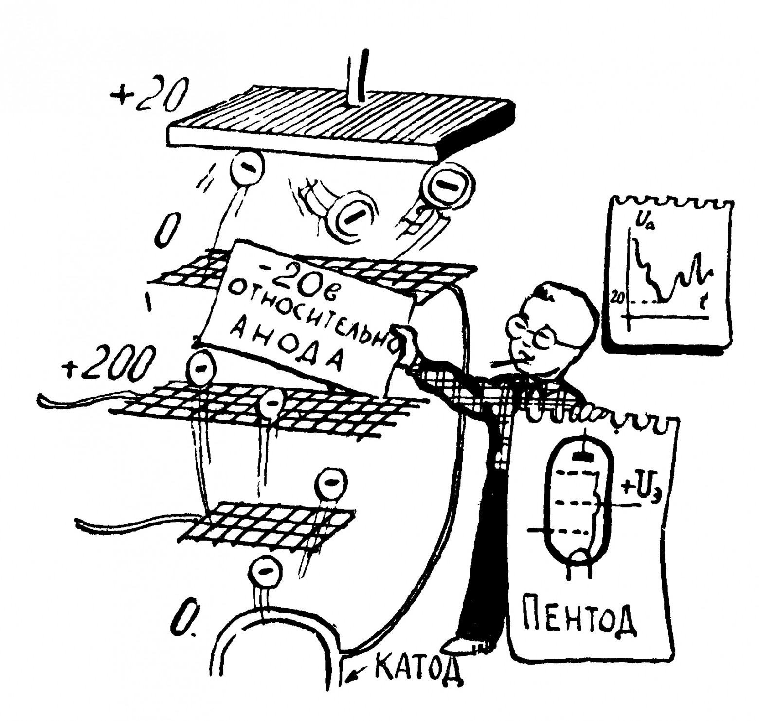
The Pentode: A Third Grid
The answer to the dynatron effect was — naturally — yet another grid. In 1926, Bernhard Tellegen at Philips added a third grid, called the suppressor grid, between the screen grid and the anode. This suppressor grid was typically connected to the cathode (ground potential).
The suppressor grid created a low-potential barrier that repelled the low-energy secondary electrons back toward the anode, while the high-energy primary electrons sailed right through. Problem solved — cleanly and elegantly.

The pentode became the workhorse of electronic design for decades. It offered high gain, good high-frequency performance, and clean output characteristics. Pentodes found use in everything from radio receivers and transmitters to early computers and industrial control systems.
The Beam Tetrode: An Alternative Path
There was another solution to the dynatron effect that didn't require a suppressor grid. In the 1930s, engineers developed the beam tetrode (also called a beam power tube), which used a clever physical design to achieve the same result.
Instead of adding a third grid, the beam tetrode used carefully shaped beam-forming plates to concentrate the electron flow into narrow, dense beams directed at specific areas of the anode. This beam concentration created a virtual suppressor — a region of high electron density near the anode surface that repelled secondary electrons just as effectively as a physical grid.
The beam tetrode had a practical motivation beyond engineering elegance: Philips held the patent on the pentode's suppressor grid. The beam tetrode, developed primarily by the British MOV/Marconi-Osram and later adopted by RCA, provided a way to achieve pentode-like performance without infringing Philips' intellectual property.
Beam tetrodes became especially popular in audio power amplifier applications, where their characteristics produced a warm, pleasing distortion at high signal levels — a quality that guitar amplifier designers still prize today.
The Bigger Picture
The progression from diode to triode to tetrode to pentode is a beautiful example of iterative engineering. Each innovation solved a specific problem but introduced a new one, driving further innovation. The parasitic capacitance of the triode led to the screen grid; the secondary emission problem of the tetrode led to the suppressor grid; and the patent restrictions on the pentode led to the beam tetrode.
By the time transistors arrived in the late 1940s, vacuum tube technology had reached a remarkable level of sophistication. The principles discovered during this era — feedback, amplification, impedance matching, frequency response — remain fundamental to electronics today, even though the devices themselves have largely been replaced by solid-state components.
Vacuum tubes haven't entirely disappeared, of course. They persist in high-power radio transmitters, microwave ovens (the magnetron is a type of vacuum tube), audiophile amplifiers, and guitar amps — anywhere their unique characteristics offer advantages over transistors.
FAQ
What is this article about in one sentence?
This article explains the core idea in practical terms and focuses on what you can apply in real work.
Who is this article for?
It is written for engineers, technical leaders, and curious readers who want a clear, implementation-focused explanation.
What should I read next?
Use the related articles below to continue with closely connected topics and concrete examples.