UPS!...We Did It Again: How We Spent a Year of Development to Stop the UPS from Swelling
The Wiren Board engineering team shares a detailed case study of how they investigated and solved battery swelling in their WB-UPS v.2, ultimately redesigning the entire device into the much-improved WB-UPS v.3 with smart charging, Modbus RTU interface, and parallel operation capability.
We have to admit — we consider our previous uninterruptible power supply, WB-UPS v.2, a failure.
Not because we made a mistake somewhere, or cut corners, or skimped on parts. No, we used decent components and did everything according to the manufacturer datasheet recommendations. But that wasn't enough. We had to replace a noticeable portion of devices (~1.5%) under warranty — after several months of continuous operation, the batteries "swelled up," though they continued working. It was clear something had to be done.
We stopped producing the devices and began developing a new model. We had to do quite a bit of research and experimentation, and it was worth it — WB-UPS v.3 is a cut above, at roughly the same price. And it even includes some of our know-how. Now let's get into the details.
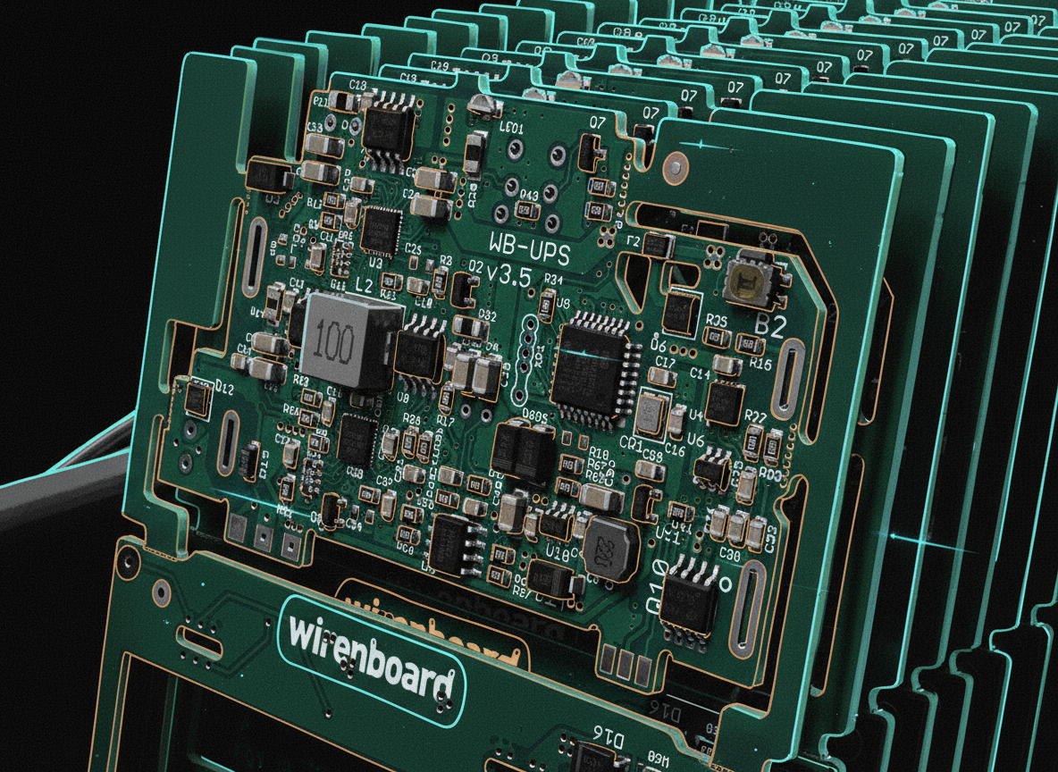
WB-UPS — What Is It?
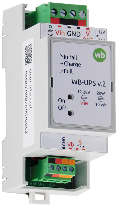
WB-UPS v.3 is a compact uninterruptible power supply with onboard lithium-ion batteries.
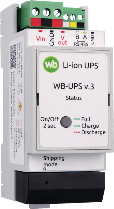
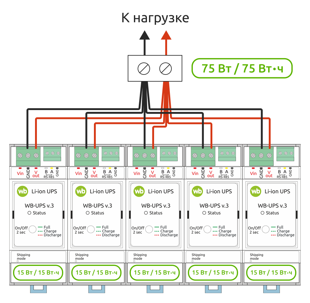
It mounts on a DIN rail, occupies only 2 DIN units, and when input voltage is absent, provides output voltage in the range of 9–25 V (configurable) for loads up to 15 W (briefly up to 20 W). Moreover, you can connect several WB-UPS units in parallel, activate parallel operation mode, and thereby sum up their watts and watt-hours.
The development team's priorities were compactness and affordability.
Why Did the Batteries Swell in WB-UPS v.2?
In defense of the second version, less than 1.5% of devices were returned to us under warranty. The rest work as intended. And in our defense, we thoroughly tested both prototypes and production units. We pushed them into extreme charge/discharge modes, heated them in thermal chambers... and in our experiments, the batteries behaved quite decently — they worked and didn't swell.
Analysis of the units returned to us showed that their electronics were perfectly fine, no malfunctions. We checked every possible hypothesis: charge circuit failure (no, they worked perfectly), cell imbalance (voltages were equal and within spec), over-discharge or overcharge (none), and so on.
Incidentally, the batteries themselves, though swollen, worked just fine.
Maybe It's the Batteries Themselves?
We bought cells from the same manufacturer, through the same supplier. Doubts crept in: could the supplier be shipping us something different? Could the manufacturer's quality be inconsistent? Testing the latter hypothesis was straightforward: we analyzed the correlation between returns and the cell batches used in them. We found no correlation, so that wasn't it.
We also had doubts about the specific cell model. We spent a long time corresponding with the manufacturer through the distributor, but in the end they just shrugged: they found no problems with the circuit, charging conditions, discharge conditions, etc., and the problem didn't reproduce on their end. Moreover, the distributor's own statistics didn't support our claims: not a single other customer experienced swelling with these same cells.
We could have simply switched manufacturers or chosen a different model, but without understanding the cause, it would have been a lottery. Remember — cells swelled only after at least a year of operation!
Could Operating Conditions Be the Problem?
This thought was prompted by unhappy customers who, after getting their WB-UPS replaced with a new one, experienced the same thing again — cells swelled. We started not only collecting UPS units with swollen cells for investigation, but also visiting customer sites.
What could even differ in operating conditions? Temperature, charge/discharge cycles, connected load power. Imagine our surprise when at "problematic" customers with supposedly "harsh" conditions, we found UPS units connected to tiny loads, sitting in cold electrical panels, that had probably never once fully discharged!
Meanwhile, we tried everything to make these cells swell in our lab. The only way we managed to reproduce the problem was placing WB-UPS v.2 in a thermal chamber at very high temperature while simultaneously cycling it at maximum power. But this experiment wasn't very useful — customers didn't operate their WB-UPS under such conditions.
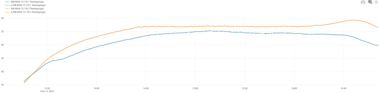
Of course, during all our investigations, we found several real problems in WB-UPS v.2. For example, we determined that at high input voltage, the UPS heated up noticeably during cell charging. The cause was the DC-DC converter: in one of the revisions during the semiconductor crisis, we replaced the step-down regulator from the scarce AOZ with Rychip across all our devices, but only in WB-UPS v.2 did it operate simultaneously at high current and with large input and output voltages. In precisely this mode, its efficiency was far below the analog's (and the datasheet's), and we missed this combination during testing of both the chip and the device.
We spent an enormous amount of time on research, fixes, and more research. Unfortunately, everything we discovered had no impact on cell swelling.
All we knew in the end was that good cells, despite correct circuit design, began generating gas in our UPS units, and after several months could become 1.5–2 times thicker. Their other parameters didn't deteriorate. This didn't lead to explosions or fires, but it scared people, and leaving cells in that condition wasn't right.
What Theory Says
Theory was tough. Finding proper information from manufacturers about cell degradation while in a charged state is a real problem. The entire Internet is flooded with nothing but marketing presentations. Automakers are actively doing R&D but don't share information. If you want to dive as deep into the topic as we did, we recommend starting with the book Beard — Linden's Handbook of Batteries (McGraw Hill, 2019) — we couldn't find anything more recent. And listen to lectures by Dr. Jeff Dahn, especially his Q&A sessions.
We also traveled to the Electronica exhibition in Munich and tried to extract maximum information from every cell manufacturer — that was useful too.
P.S. If you have higher-quality information, please share links — our engineers would be very grateful.
It became clear that the cause of swelling wasn't singular — it was a complex of factors. Batteries in UPS devices "live" under the harsh conditions of constant full charge, in a state of "always ready." Inside electrical panels, temperatures are often high. It turned out that gas generation accelerated dramatically when cell voltage was high. The combination of high voltage and high temperature was especially damaging. The specific electrolyte composition differed even among cells with "identical" chemistry and also affected gas generation.
"High voltage" in this context means the standard 4.20 V cutoff during charging. The later you stop charging, the more energy you can push into the cell. But standard voltages are optimized for the standard usage profile: charge-discharge. During discharge, cell voltage drops very quickly and steeply, and the rate of parasitic chemical reactions drops too. The battery "passes through" the dangerous zone and spends most of its time at safe voltages. But in a UPS, the battery is always charged.
In short, our conclusion from everything we researched, read, and heard was this: to ensure proper operating conditions for batteries working under the harsh conditions of a UPS, you shouldn't charge them to nominal — you need to stop the charger earlier. Nominal values are given for devices operating in charge/discharge mode, and this is a different situation.
The Manufacturer Knew All Along!
When we had already figured out the issue and, in a casual conversation at another exhibition, shared our conclusions with the technical director of the pouch cell manufacturer, it turned out we had reinvented the wheel. He immediately suggested undercharging the cells. He said our cells were adapted for low ambient temperatures, their electrolyte wasn't optimized to minimize parasitic reactions, and they had cells far better suited to our operating conditions. But this information hadn't reached us in time through either the manufacturer's engineers or the distributor's specialists, even though we had pestered them relentlessly. Funny and sad at the same time.
The conclusion was made — now it needed to be implemented in hardware. And since we were already redesigning the device, we added useful new features right away. Let's look inside WB-UPS v.3.
What's Inside WB-UPS v.3
Microcontroller
We spent a long time trying to find off-the-shelf chips with the logic we planned to implement — it didn't work out. We'd have to write the firmware ourselves. So the third version got a microcontroller that manages everything.
RS-485 Interface
Since we already had a microcontroller, it would have been a shame not to give the device an interface for configuration, control, and monitoring. So we did — Modbus RTU.
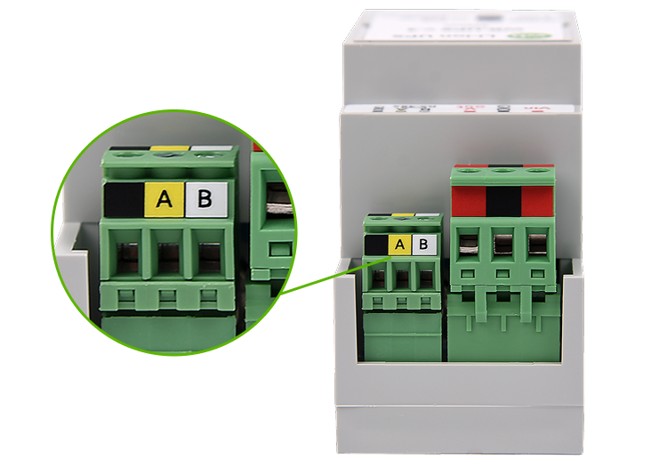
Now WB-UPS can be easily integrated into automation and dispatch systems.
Reliable Batteries
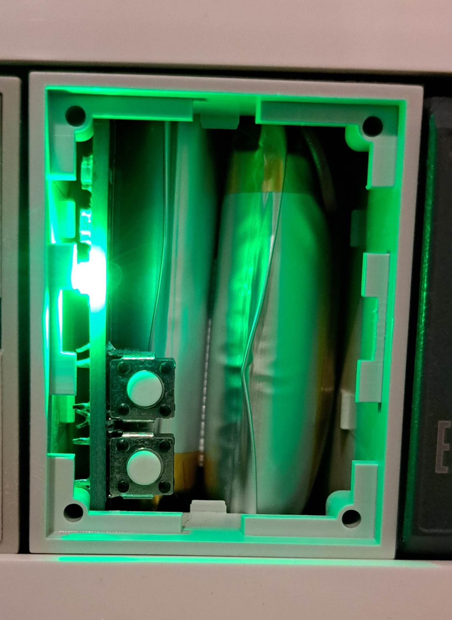
In WB-UPS v.3, we use cylindrical cells in the 18650 form factor. The same ones that have been used in our WBMZ-BATTERY modules for many years. To date, tens of thousands of these cells in our devices have been operating at real sites for several years, with minimal failure statistics. We use NMC cells from a well-known manufacturer. Their capacity is 2600 mAh. There are models on the market with 4000+ mAh, but we deliberately use only what's been proven over time.
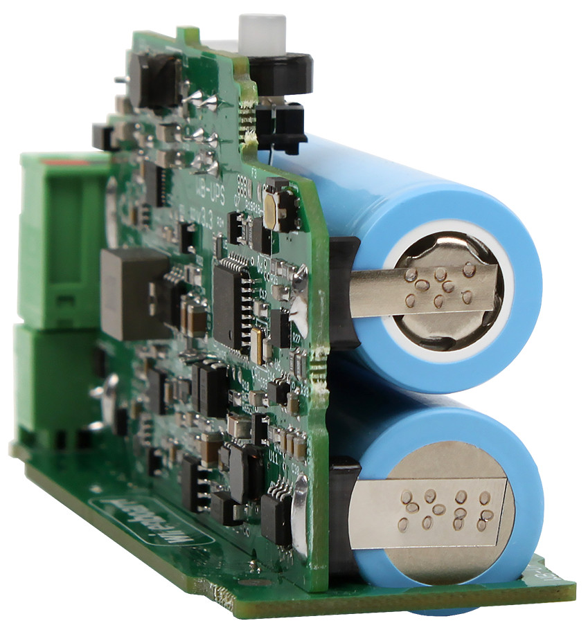
Importantly, cylindrical cells are inherently rigid with a metal casing. When gas forms and pressure builds, they vent through a built-in safety valve. No deformation occurs.
Also, manufacturing 18650 cells is technologically more complex and expensive, which eliminates amateur manufacturers and reduces the risk of encountering their products.
Smart Charger
We now charge cells not to 4.2 V, but to approximately 4.05 V per cell (~8.1 V for the battery). Yes, this reduces usable capacity by ~15%, but significantly extends cell lifespan.
Off-the-shelf charge controllers that allow an arbitrary output voltage virtually don't exist, so we assigned this function to the device's microcontroller right away. But we also use a charge controller with fixed thresholds (4.1 V, 4.2 V, 4.25 V per cell). If the microcontroller (for any reason) doesn't shut off the charger in time, the hardware charge controller will do it at 4.1 V per cell. If something goes wrong there too and voltage keeps rising, there are two more hardware protections. One disconnects the battery from the circuit via separate transistors at 4.25 V. The other, when exceeding 4.3 V, burns a harakiri fuse, physically severing the cell from the rest of the circuit.
Charge current is configurable, defaulting to 600 mA. If current exceeds the setpoint, the charger will be shut off by software. If software doesn't shut it off, hardware protection kicks in. And in case of a short circuit, the fuse burns.
Of course, there's a cell voltage balancing circuit. It ensures equal charge, preventing one cell from being overcharged if the other is depleted.
We disabled the trickle charge function, even though the charge controller supports it.
Why We Disabled Trickle Charge
The function works simply: while battery voltage is below the minimum threshold, charging proceeds at 10% of nominal current. Once the threshold is exceeded, current steps up to nominal. The hardware charge controller handles this; the microcontroller has no involvement.
The function is useful for deeply discharged batteries, allowing an attempt at recovery. But during prototype testing, it caused problems in "transport mode" (described below): with a deeply discharged battery, due to chip behavior quirks, exit from transport mode didn't happen on the first attempt. Since WB-UPS won't allow the battery to discharge that far, we disabled the function.
In addition to voltage and current, cell temperature is continuously monitored via a thermistor installed between the cells. If temperature exceeds +50°C or drops below +5°C (to prevent dendrite growth), the microcontroller won't enable the charger — or will disable it if it's on. There's also a second protection layer here — hardware — that blocks the charger at unsafe temperatures. Once temperature returns to normal, charging resumes.
Where to Place the Thermistor?
In WB-UPS v.2, the thermistor was simply mounted on the PCB. The assumption was that cell temperature shouldn't differ much from the temperature inside the enclosure. Modeling heat transfer processes in such a system is extremely labor-intensive.
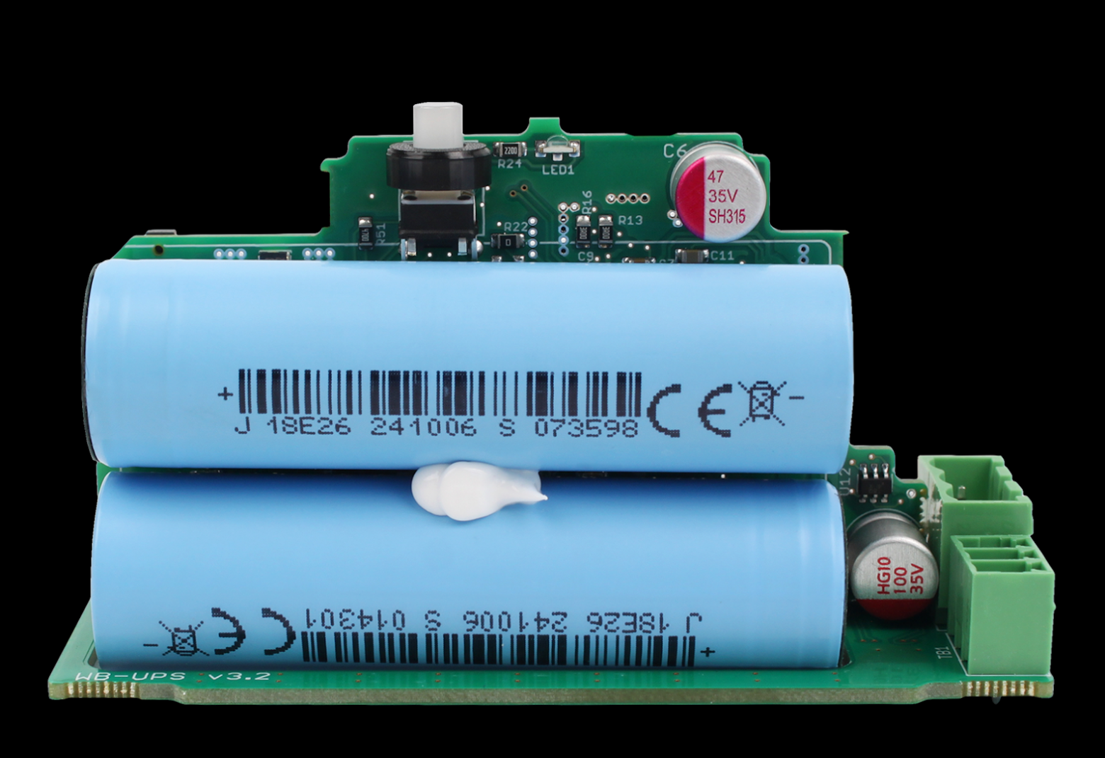
In WB-UPS v.3, we decided to study this question. We experimented on a prototype and confirmed that the thermistor was being heated by converter components, showing inflated values. We clamped the sensor directly between the cells and ran more tests — temperature was still inflated by a couple of degrees. It turned out the thermistor's leads were conducting heat from surrounding components. Seems trivial — just a couple of degrees — but when temperature is close to the blocking threshold, those degrees matter.
The problem was solved by using a special high-thermal-conductivity sealant that dramatically increases the sensor's heat exchange surface area with the cells. This sealant is clearly visible in the photo. Now cell temperature is measured accurately.
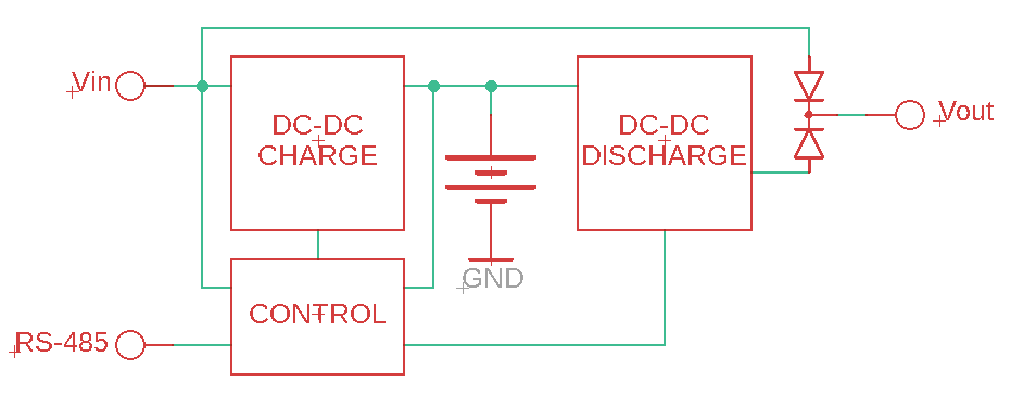
Smart Discharge Circuit
By "discharge circuit" we mean the boost voltage converter itself and all the circuit solutions that handle switching the UPS to battery power and protective functions.
While WB-UPS v.2 had two fixed output voltage values selected by a switch, the output voltage can now be set anywhere in the 9–25 V range by simply writing the appropriate value to a Modbus register.
The boost converter runs continuously unless turned off by the button. The WB-UPS input and converter output are connected through back-to-back "ideal diodes."
What Is an "Ideal Diode"?
An ideal diode is an electronic circuit consisting of a field-effect transistor (MOSFET switch) and a control circuit. It mimics the behavior of a regular diode — current flows through the switch in only one direction.
A real diode drops noticeable voltage when current flows through it, due to the potential barrier (above 0.6 V for silicon, above 0.2 V for Schottky diodes). This means the output voltage is lower by that amount, and power is dissipated across the diode.
A MOSFET switch has no potential barrier — just channel resistance (very small when open) — so these drawbacks don't apply.
If WB-UPS input voltage is higher than converter output, the converter's diode is blocked and current flows only from the input. If it drops lower, the input diode instantly blocks, the converter diode opens, and current flows from the converter. There are no sags on the load.
Proper converter voltage configuration is important — it should be slightly below input voltage. Incorrect settings, or fluctuating input voltage, can drain the battery. To simplify things for users, we provided an automatic mode: if input voltage exceeds 11 V and remains stable for more than 10 seconds, the microcontroller measures it and sets converter voltage 0.7 V lower. Use it if convenient; if not, set a fixed output voltage. Important note: input voltage is not limited or cut off from above.
Why Not Cut Off Input?
We debated whether the ability to remotely disconnect the load while external power is present was needed. Adding another power switch between input and output isn't hard, but there are drawbacks:
- Another potential failure point — the switch itself and its control circuit;
- Another element in the maximum-current path that drops voltage and generates heat;
- Increased device cost.
Weighing pros and cons, we decided the harm outweighs the benefit. And disconnection can easily be implemented with an external relay module.
When input voltage is absent, the discharge circuit can be turned off by Modbus command or the button on the case. And turned back on. This enables scenarios like: power sensors from a separate WB-UPS and, when the facility loses power, periodically turn on their power, take measurements, and turn it off again. This mode can multiply autonomous operating time by several times.
But there's one subtlety to know: when starting WB-UPS from battery (with no external power), its output voltage will be 11.5 V.
Why 11.5 V?
We're concerned about this scenario: a customer connects WB-UPS to a 12 V power supply and is therefore confident voltage can't exceed 12 V (subconscious assumptions). But WB-UPS is configured for a higher output voltage — for example, because it previously operated in 24 V circuits. Then, when turned on by button without external power, the expensive downstream equipment gets powered by higher voltage and burns. Risk? We think so, for all consumers. And the function of battery startup above 12 V is needed by very few. So we decided to cap it at 11.5 V and see. If customers request we remove this limitation, we'll release a special firmware.
Output current is limited.
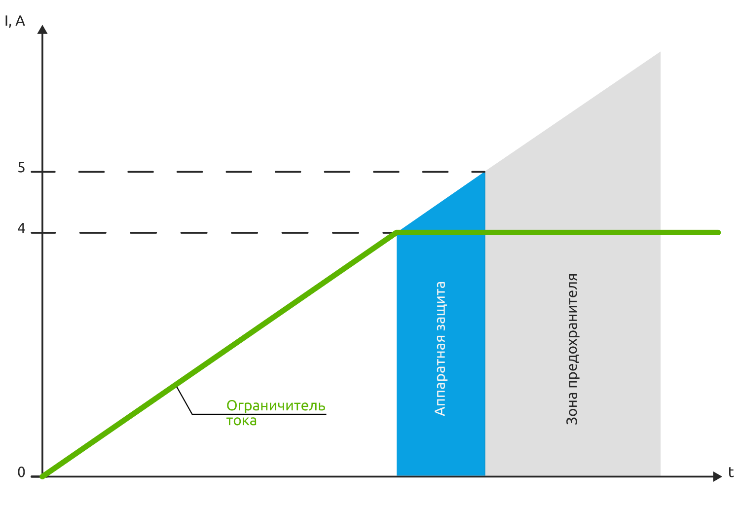
When reaching 4 A, the converter switches to current stabilization mode — it reduces voltage until current equals 4 A. Down to 0 V, which also handles overload and short-circuit protection. If for any reason current exceeds 4 A, hardware protection shuts down the converter. And above 5 A, the fuse burns.
As with the charger, the discharge circuit monitors cell temperature. If they heat above 60°C, the converter shuts down until temperature returns to normal — to avoid heating the cells further.
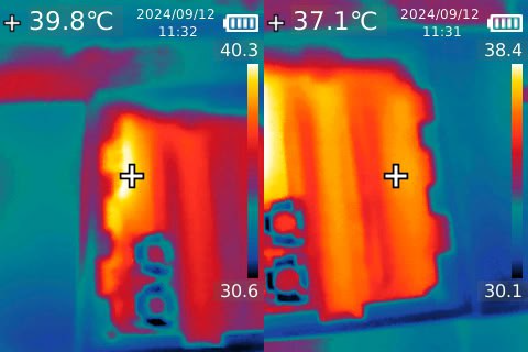
Temperature and Nominal Operating Mode
Early prototypes ran noticeably hot — hotter than desired. Thermal imaging showed the main heat source was the inductor in the boost converter. It was operating in nominal mode but had relatively high resistance and core losses, reducing efficiency. We had to "re-size" the inductor and reduce gate drive resistances of the switching transistors to speed up their operation and reduce switching losses. As a result, board temperature dropped and efficiency improved.
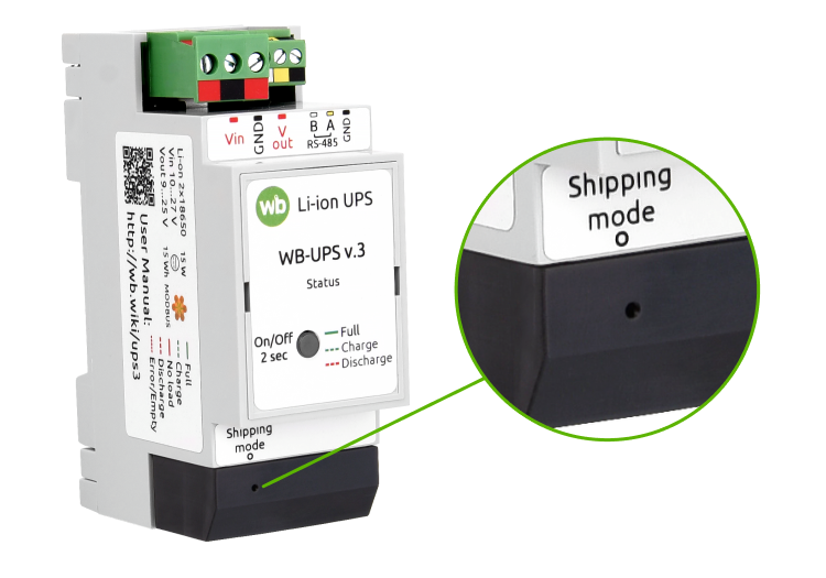
Transport Button
WB-UPS v.3 gained a hidden button that activates "transport mode." This mode is needed by both us and our customers.
We can't ship batteries separately from the device — they're soldered in. And the 210 µA the device draws when off can (in about a year) drain them completely while devices sit in a warehouse or travel to the customer.
Our customers' process typically has two stages: panel assembly/commissioning and on-site installation. Months can pass between stages. Again, it would be nice to disconnect the batteries.
The transport button does just that. It doesn't physically disconnect them, of course, but it dramatically reduces current draw — to 70 µA. In transport mode, WB-UPS can't be turned on by button; external power must be applied to wake it. All this allows batteries to stay alive and healthy for many months while they reach their permanent workplace.
The Patient Is More Dead Than Alive
We encountered a problem where even our own engineers, closely familiar with WB-UPS, would bring a perfectly working device that had come to them for testing with the comment: "dead." Though the device was simply in transport mode. Another trick of our minds — the device doesn't respond to the button, so it must be dead. We had to emphasize this in the documentation. And we still expect support tickets saying "I bought a brick."
Button-Indicator
This is a small detail, of course, but a useful one. The device features a button with a built-in light indicator.
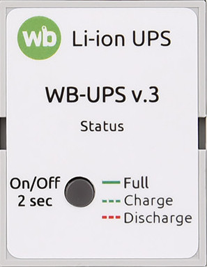
Besides turning off the voltage converter, the microcontroller recognizes 4 types of presses (short, long, double, short+long). It also counts such presses and generates corresponding fast Modbus events. All of this allows using the button in automation scenarios: shutting down multiple WB-UPS units with one button press, for example. Or using different press types to shut down different WB-UPS units. Some of our engineers think this is silly, but the development team is confident it's a useful feature. Especially since it was easy to implement.
We also loaded up the indicator. Its blinking pattern now conveys five statuses:
- Power present, batteries charged;
- Power present, charging in progress;
- No power, idle;
- No power, load powered by battery;
- There are problems.
That's about everything we can find inside the device.
New Features
With the addition of a microcontroller, WB-UPS v.3 gained convenient new features.
Super Feature — Parallel Operation
We already mentioned this — multiple devices can be connected in parallel, providing combined power and battery capacity. Typically with such connections, an imbalance problem arises: measurement and setpoint tolerances cause the UPS with higher output voltage to be overloaded, shut down, and trigger cascading shutdown of remaining devices. Some balancing is needed.
And we have everything necessary for that: we measure current and know cell parameters. Our engineers experimented, developed, and implemented a balancing algorithm. We won't share the details — it's our know-how. We'll just say that we solved the balancing problem. In testing, we connected 10 devices and ran them through all modes. At 150 W load (200 W briefly). It's unlikely anyone would need to connect more UPS units — at that point it makes more sense to divide the load into groups and power them separately.
Achieving perfect balance is hampered by measurement tolerances. And wire resistances, if they differ between UPS units. So we recommend star topology (not daisy-chain) in this mode, with equal-length wires, adequate cross-section, and a small power margin on the devices themselves.
Don't think the devices communicate with each other. The algorithm allows each device to operate using only its own data: voltages, currents, cell internal resistance.
About Internal Resistance
We measure cell internal resistance during device testing. During testing of the next batch, we noticed resistance had dropped almost 2.5 times — from ~37 mOhm to ~15 mOhm. Even though it was the same cell model.
Lower internal resistance is a plus. The cell heats less and loses less energy at high currents. But the fact of the change was concerning: what if something else changed? We ran tests — no, the charge/discharge curves matched, capacity was the same.
We also sent an inquiry to the manufacturer. And received a curious technical term in response: 双极耳. After studying specialized Chinese-language articles, it turned out to be the "dual tabs" technology — double leads from each electrode.
Inside the cell is a rolled-up multi-layer "sandwich" of foil (positive and negative electrodes), dielectric, and electrolyte. In the classic design, each electrode has one conductor, and current flows through thin foil across the entire roll. In the dual tabs design, each electrode has an additional conductor connected to the opposite side. Current is therefore lower, and so is resistance.
The manufacturer implemented this technology at the request of large customers. And we're only glad. We adjusted the coefficients, released new firmware. And we're glad we test every device, catching such things on the very first samples.
Modbus RTU
We already mentioned that you can control WB-UPS output voltage by writing a setpoint value to a Modbus register. And turn the boost converter on/off by writing to another register. But that's far from everything.
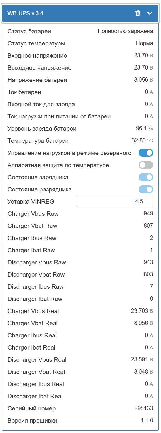
Of course, the registers contain information on all measured parameters:
- Battery charge level;
- Input and output voltages;
- Battery temperature;
- Battery current;
- Input current;
- Portion of input current going to battery charge;
- Output current when running on battery.
You can view the current operating mode, battery status, front panel button state, and press counters (short, long, double short, short+long).
You can set device parameters:
- Output voltage;
- Maximum battery charge and discharge currents.
Specialists can peek "behind the scenes" at the charger and discharge circuit, view and modify calibration coefficients, raw and processed values — so experimentation is possible too. Just be aware of what you're doing.
WB-UPS v.3 has a total of 168 registers, and we won't list them all here — they're described in detail in the documentation.
As with all our Modbus devices, the Wiren Board controller's web interface provides the ability to configure WB-UPS and view the device card. Corresponding topics are created in the MQTT broker, which can be accessed using wb-rules, or third-party automation systems running on the controller or connected to it via the network.
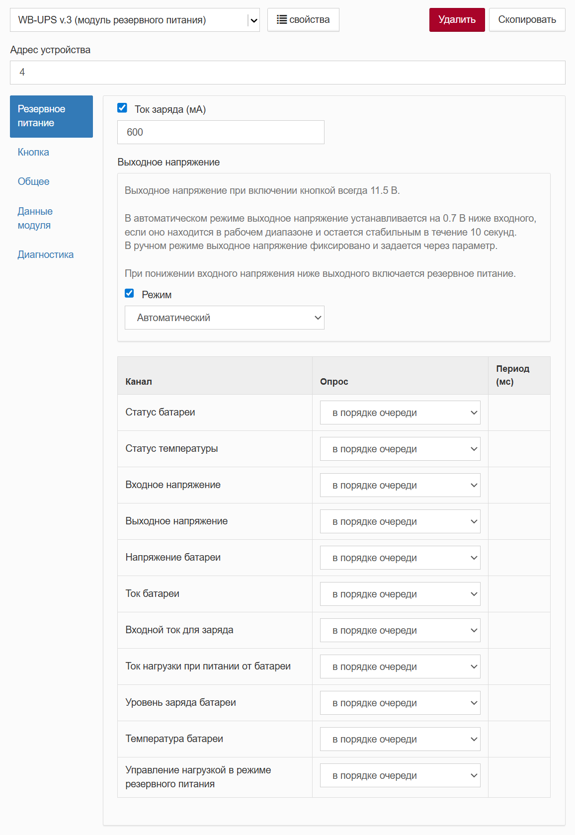
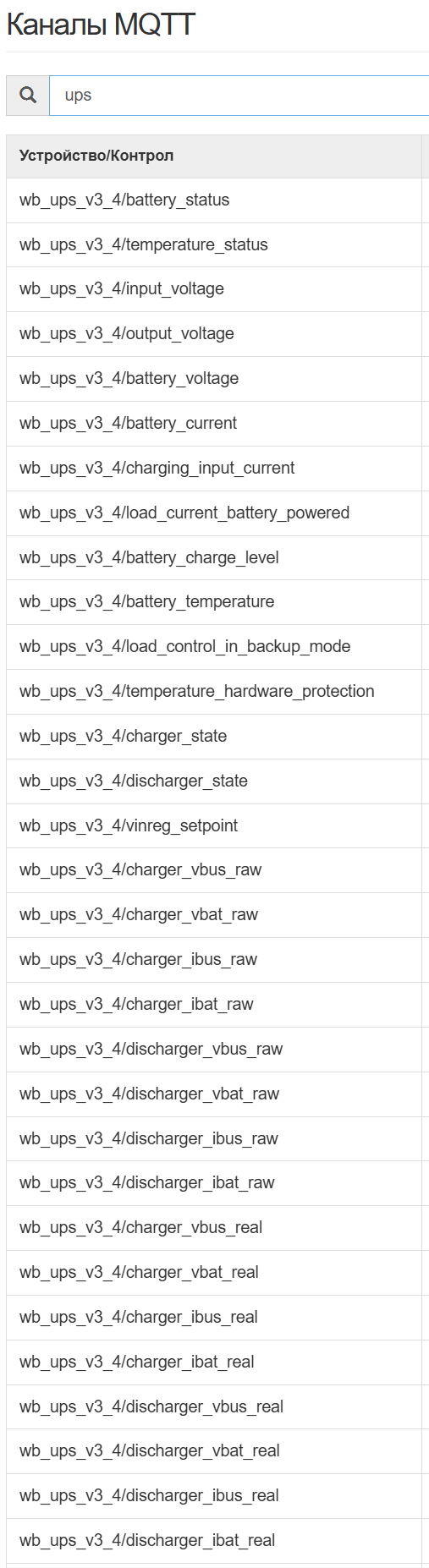
In other words, everything needed — and more — is available for integrating WB-UPS v.3 into automation and dispatch systems.
The Bottom Line
In the end, we released a device we're proud of. Yes, it could be made better. Yes, there are cooler devices on the market. But in terms of price-to-quality ratio, WB-UPS v.3 is very good. Just give it a try.
And here's a summary comparison table of versions 2 and 3.
| Parameter | WB-UPS v.2 | WB-UPS v.3 |
|---|---|---|
| Battery type | 2x pouch | 2x 18650 |
| Energy | ~10 Wh | ~15 Wh (accounting for partial charge) |
| Charge voltage | 8.4 V (4.2 V/cell) | 8.1 V (4.05 V/cell) |
| Temperature control | None | Hardware + software |
| Interface | None | Modbus RTU |
| Output voltage setting | Mechanical switch | Automatic or Modbus |
| Load control | None | When running on battery |
| Transport mode | None | Yes |
| Fuses and protection | Minimal | Multi-level, with managed fuse |
Technical Specifications
General parameters:
- Input voltage: 10–27 V
- Output voltage (on battery): 9–25 V
- Nominal power: 15 W
- Peak power: up to 20 W
- Energy: ~15 Wh
- Runtime at 15 W load: ~60 min
- Power consumption during charging: up to 6 W (at 600 mA charge current)
- Self-consumption from Vin with charged battery: up to 18 mA
- Battery draw when off: up to 210 µA
- Battery draw in transport mode: ~70 µA
Battery parameters:
- Type: 18650 Li-ion
- Nominal voltage: 3.6 V
- Number of cells: 2
Operating conditions:
- Air temperature: -20 to +45°C
- Relative humidity: up to 95%, no condensation
- Storage temperature (recommended): -5 to +35°C
- Warranty: 2 years
- Service life: 5 years
Dimensions:
- DIN units: 2
- Size (L x W x H): 36 x 90 x 58 mm
- Weight (with box): 185 g
FAQ
What is this article about in one sentence?
This article explains the core idea in practical terms and focuses on what you can apply in real work.
Who is this article for?
It is written for engineers, technical leaders, and curious readers who want a clear, implementation-focused explanation.
What should I read next?
Use the related articles below to continue with closely connected topics and concrete examples.