Why There Are No Elevators on Arduino: How an Elevator Control Board Works
A deep technical teardown of real Russian elevator control stations (UKL/UL) explaining their microprocessor boards, safety circuits, matrix wiring, and sensor systems — and why cheap microcontrollers like Arduino are fundamentally unsuitable for life-safety applications.
The Story
Relay-based elevator control stations were gradually replaced by electronic systems starting in the late 1980s. While relay systems still exist in some modernization projects, electronic controllers have become nearly universal. In online discussions, commenters frequently suggest that cheap microcontrollers like Arduino could easily handle elevator control. A notorious video even showed someone attempting exactly this on a working installation. This article explains why that's a terrible idea by examining how real elevator control systems actually work.
What Are We Looking At?
We'll examine the UL and UKL control stations — common, relatively simple Russian elevator systems that are well-suited for detailed analysis.
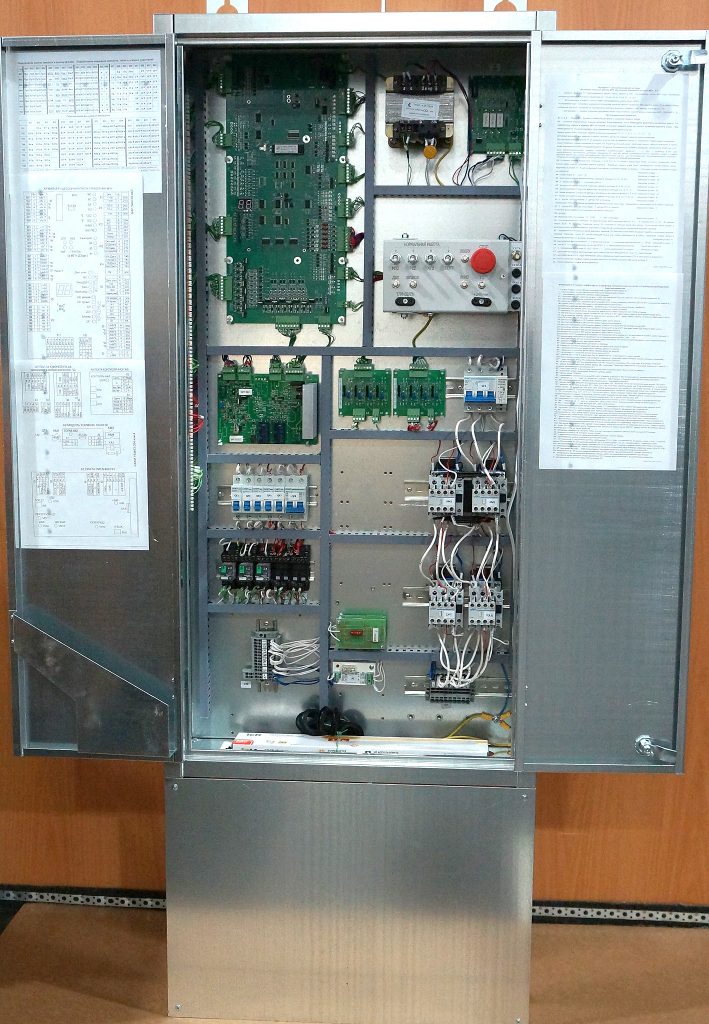
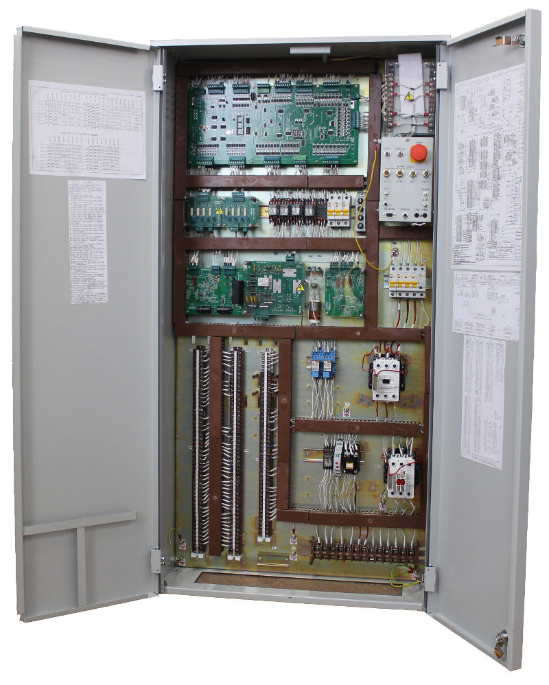
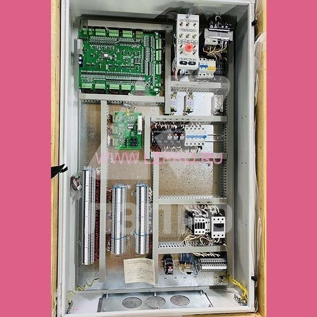
The UKL station is a cabinet containing: a control board, key boards, monitoring boards, intermediate relays, circuit breakers, starters, a control panel, and a transformer.
The UL station is a simplified variant of the same design.
The UEL station, though incompatible with UL/UKL systems, shares similar technical design principles.
What's Inside This Station?
The cabinet houses the following components:
- MPU microprocessor control board (or PU for UL stations)
- OSM-0.25 220/110/20/8 transformer
- PKF phase monitoring board
- PP power supply board
- PSK thyristor key boards
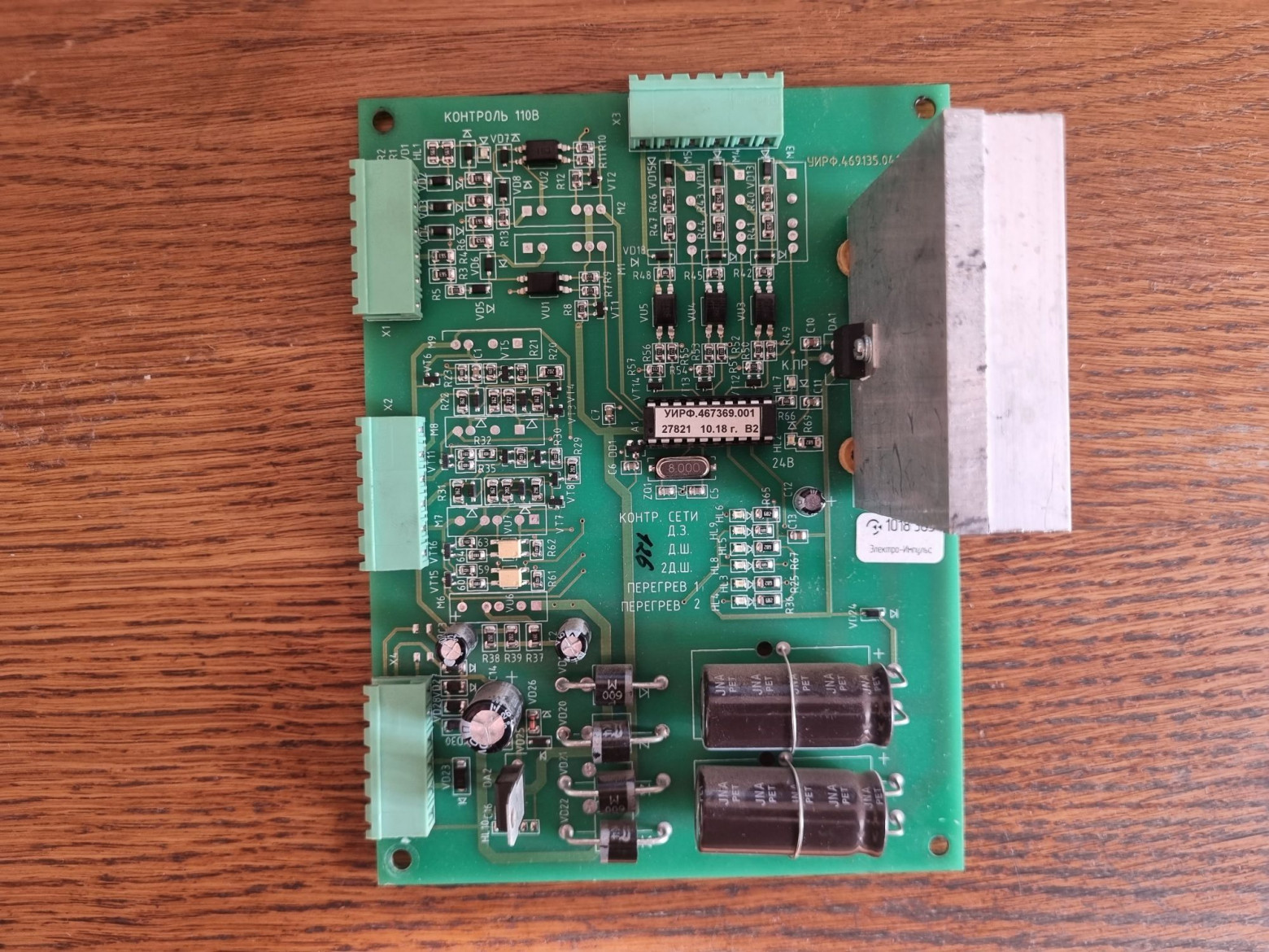
- PTZ thermal protection board
- PUT brake control board
- RC circuit board
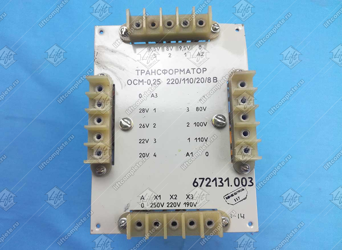
The transformer supplies system power and 110V for safety circuits and contactors.
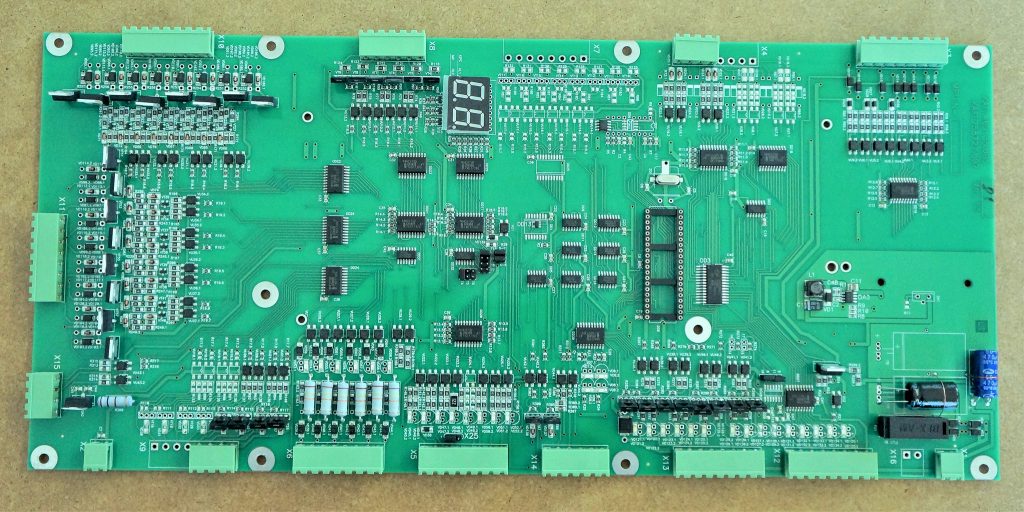
The MPU board houses the controlling microcontroller and processes all necessary signals.
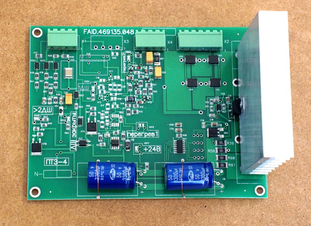
The thermal protection board contains thermistor monitoring circuits, a 24V linear stabilizer on a large heatsink, shaft protection control, and a telephone filter. The stabilizer lacks true overload protection — the LM7824 simply overheats until it fails.
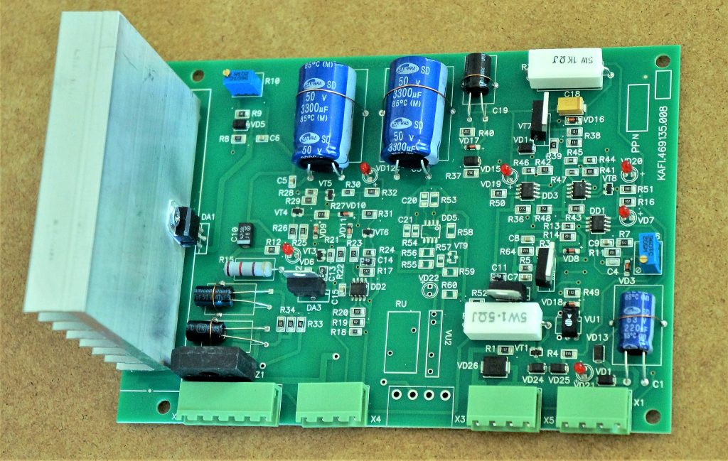
The power supply board mirrors the thermal protection board layout but adds current monitoring for 110V circuits.
The phase control board monitors phase asymmetry and correct three-phase connection.
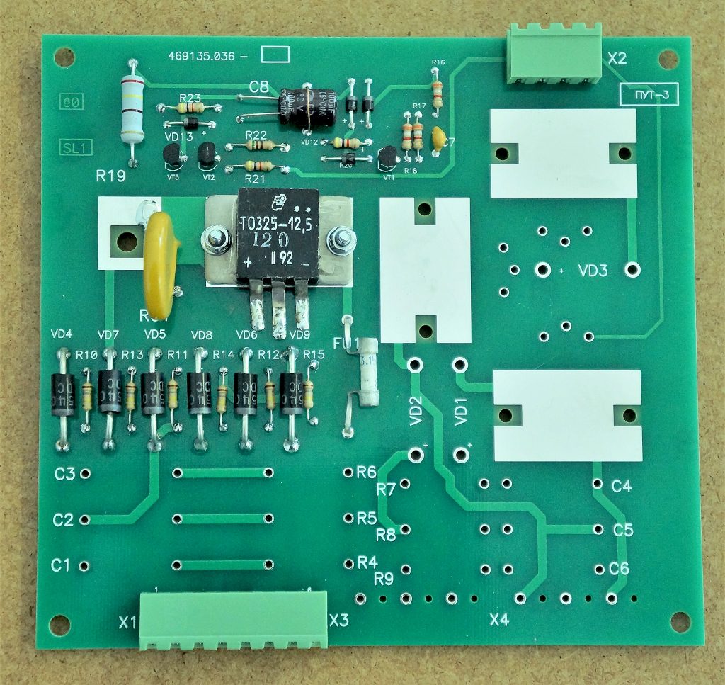
The brake control board manages electromagnetic brake actuation and cooling fan activation.
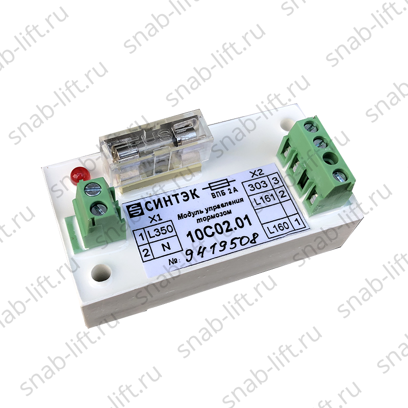
Some stations use modular replacements instead of individual boards.
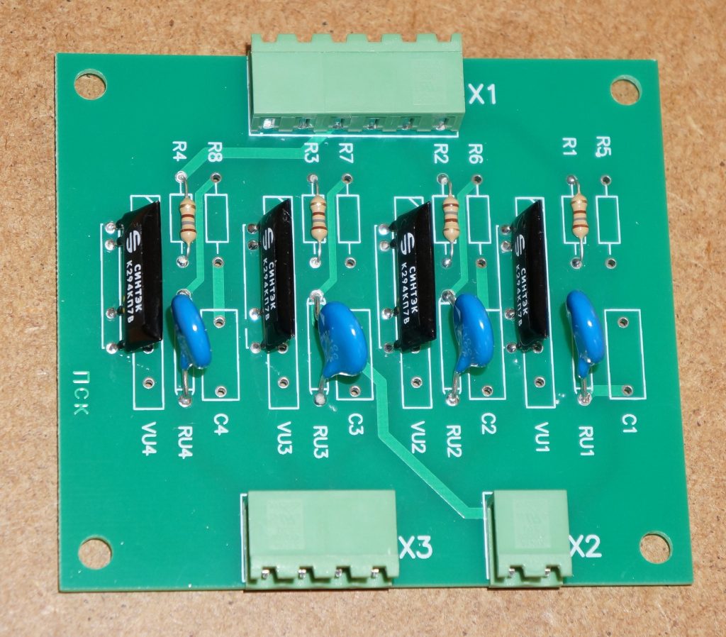
The thyristor key board contains optothyristors that control door drives and main drive starters.
Equipment Overview
These systems represent what can fairly be called "ancient technology." Many components are obsolete and the overall system lacks the reliability of modern designs. However, they remain the most common electronic control stations in most cities. Their one big advantage: complete schematics are publicly available, unlike modern proprietary systems.
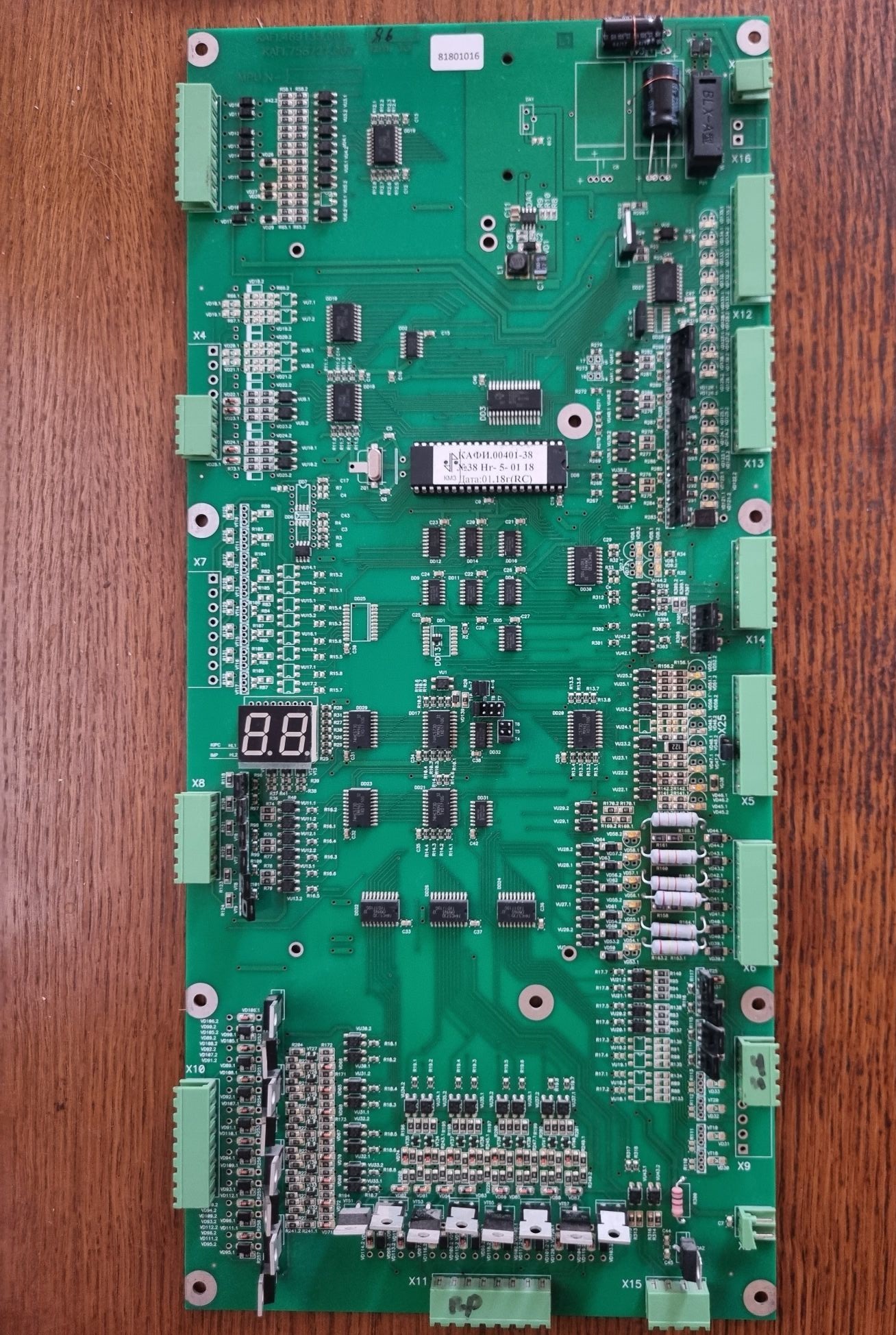
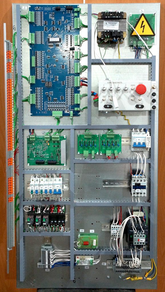
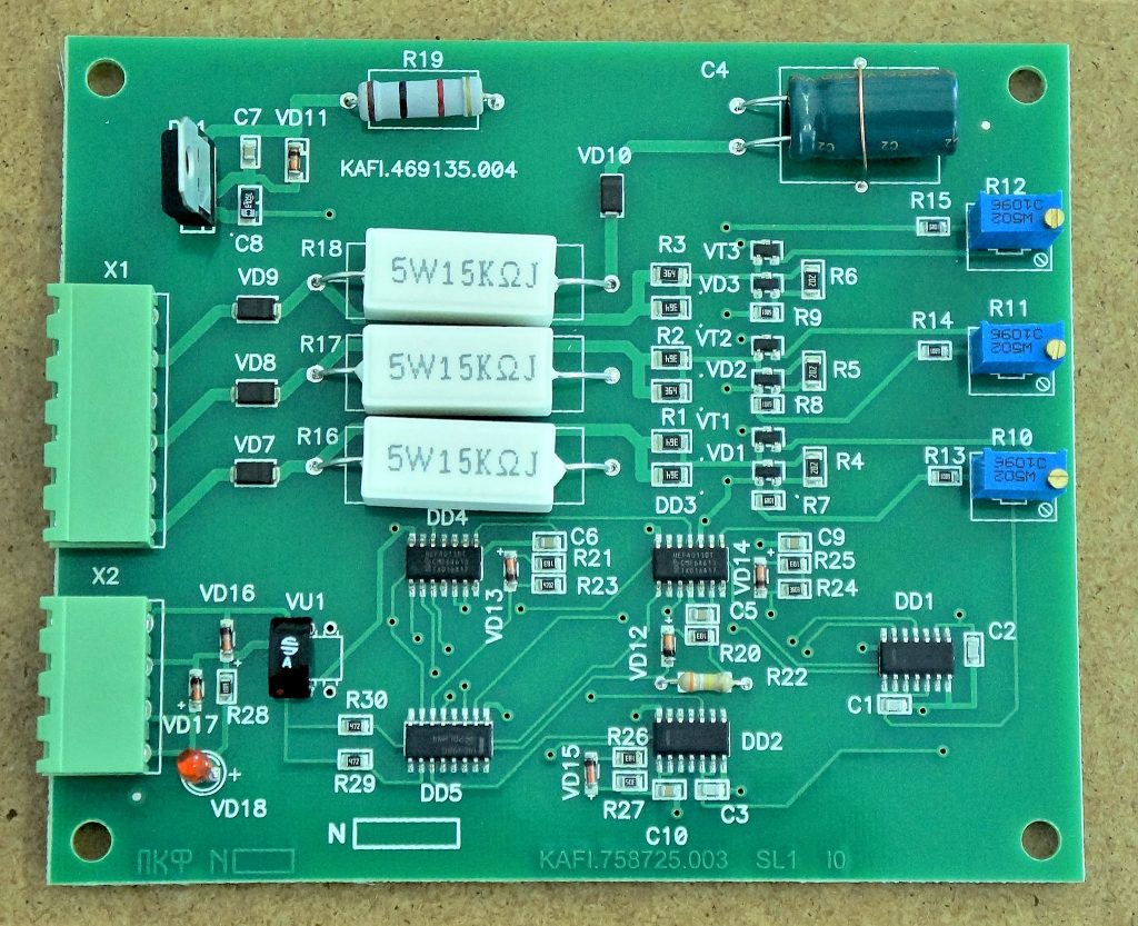
The UKL MPU board.
Optothyristor key board from UKL.
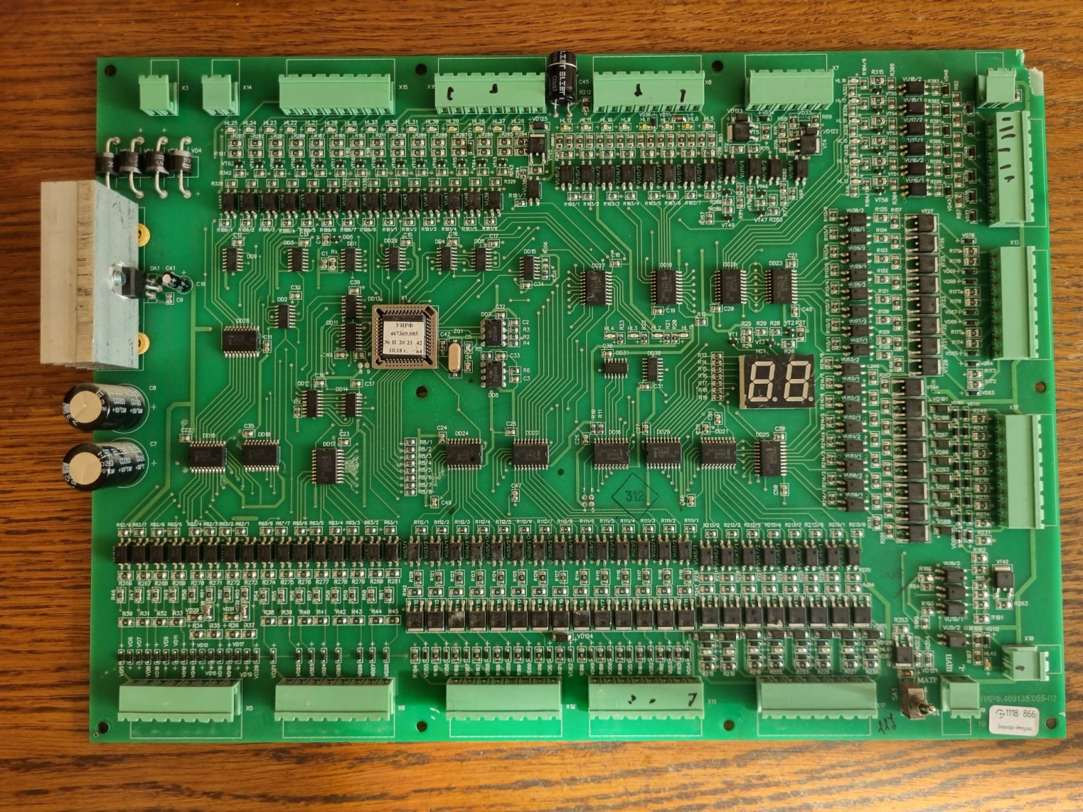
The CPU board from UEL is functionally identical to the MPU.
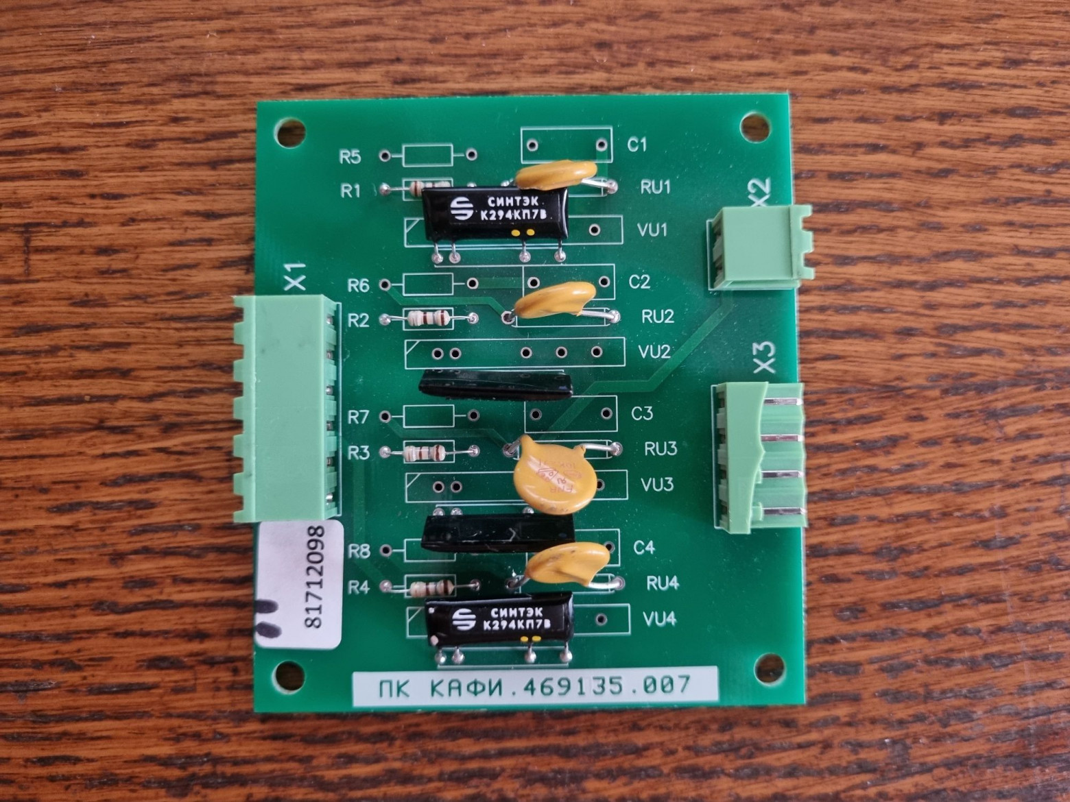
The PK board from UEL consolidates separate UKL/UL boards for phase monitoring, voltage verification, and motor temperature.
Powering Up the UKL
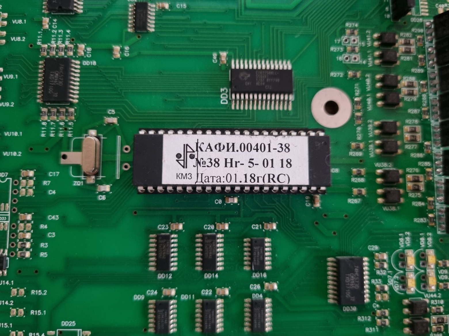
The microcontroller is a standard AT89S52.
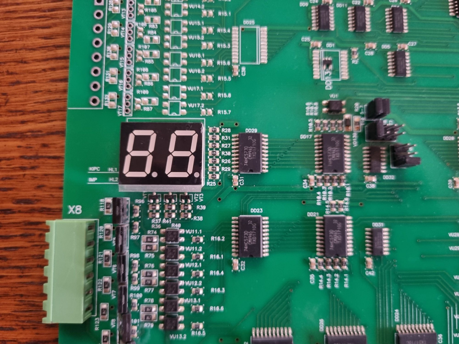
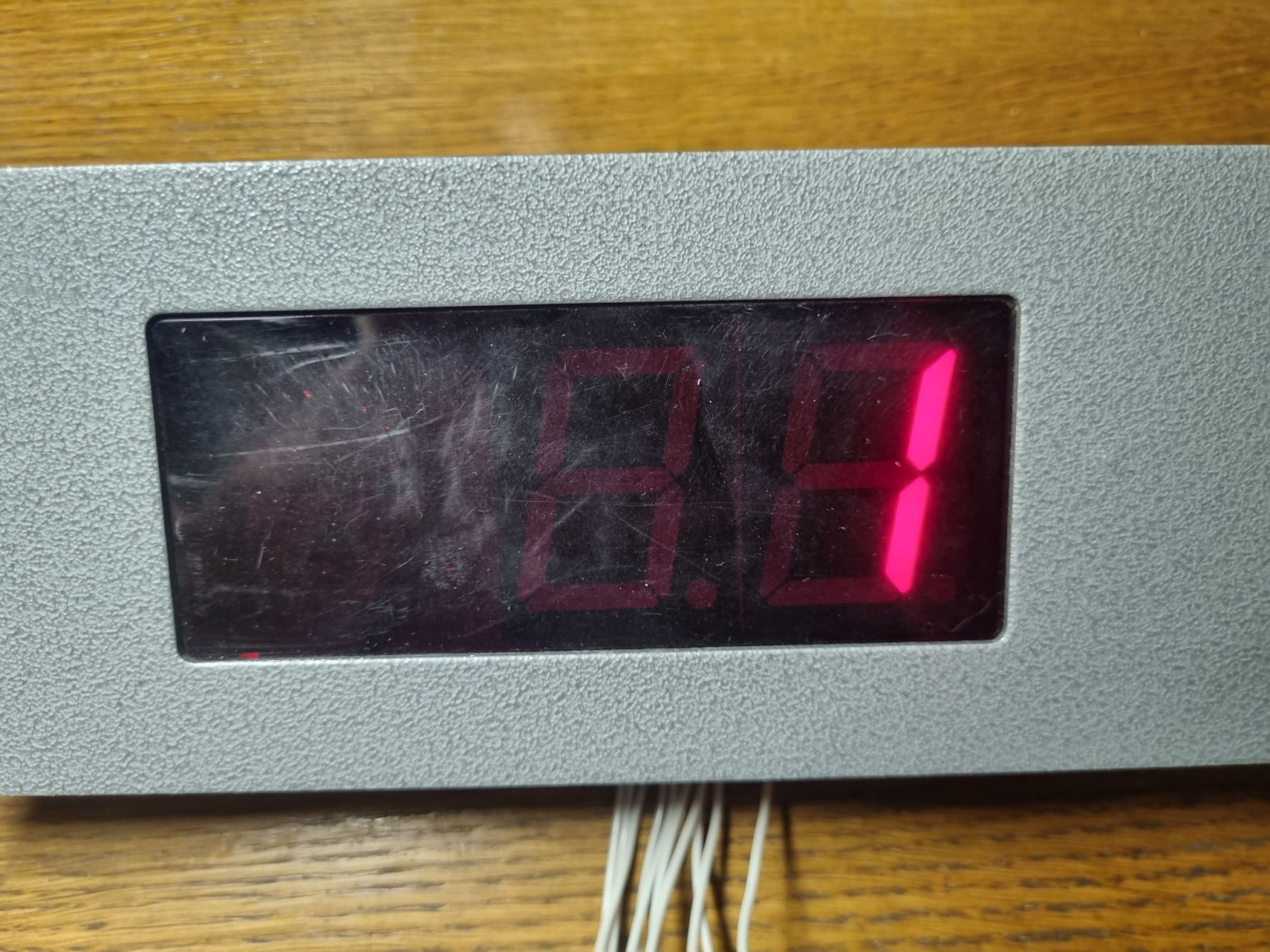
The display shows cab position, error code, and operating mode.
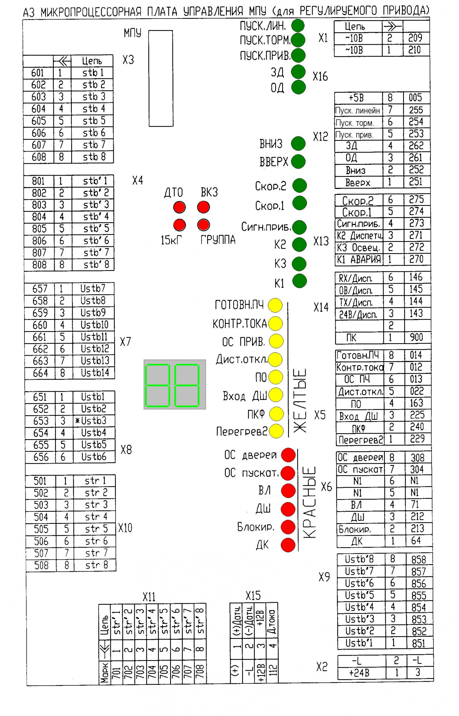
Connectors X1 and X2 receive approximately 10V AC for board power and 24V DC for control signals.
Powering the board illuminates the LEDs; the display shows "FF 41" — unknown position and missing 24V. The board functions correctly at this stage.
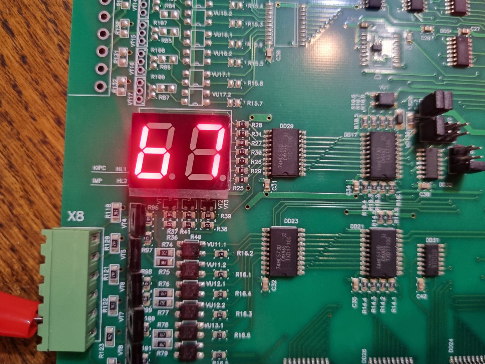
Adding 24V reveals error "b7" — input failure. Poor packaging during shipping had damaged an optocoupler.
The board uses TLP181 optocouplers. Local availability was poor, so the author ordered cheaper HPC357D equivalents at 8 rubles versus 170 for the originals, despite ordering minimums. The replacement restored full functionality.
The Matrix
Why call these systems "ancient"? Their primary weakness is the connection scheme. While appropriate when the systems were first designed, far better solutions now exist.
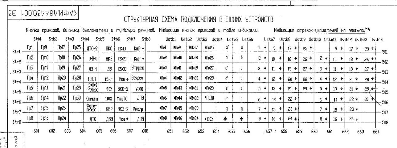
The pinout reveals control signals: motor power, direction selection, door open/close (OD/ZD), speed selection (MC/BC), dispatch, lockout circuits, and frequency converter signals. But there are no direct connections for sensors, buttons, or indicators. Instead, mysterious numbered wires labeled STB and STR appear. These are matrix rows and columns.
All devices connect via a matrix configuration — identical in principle to how digital keyboards or LED displays work. Each matrix node consists of a diode plus the connected device (button, switch, relay, indicator, or sensor). This scheme is temperamental: diagnosing failures is difficult when matrix components go bad, and it requires running numerous wires. However, its simplicity keeps it in use for older installations.
Modern elevators have moved to proper bus architectures: CAN-bus (used by Kone, Arcode, ShK6000, LiRa), RS-485, or proprietary interfaces (like OTIS Remote Link).
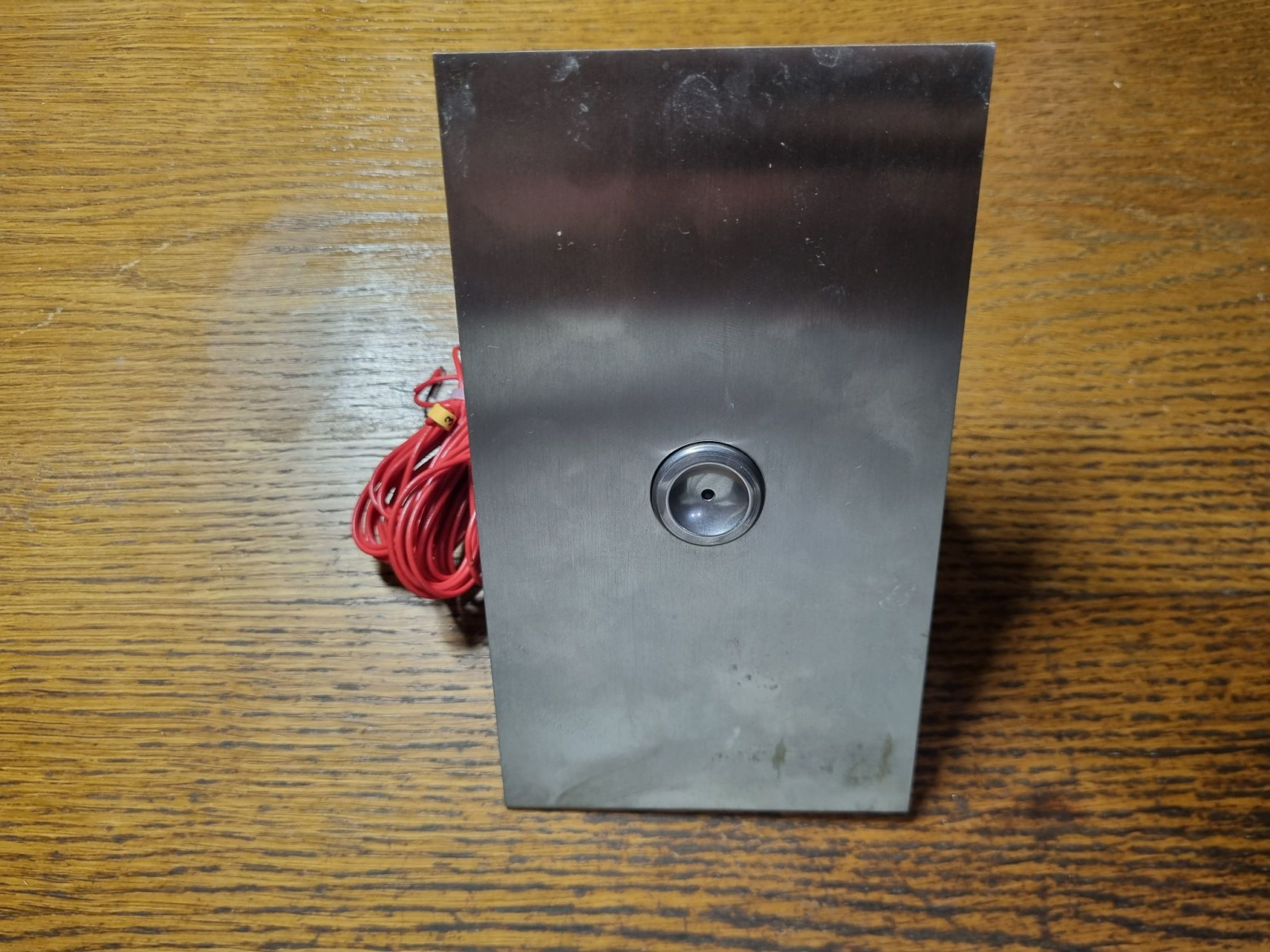
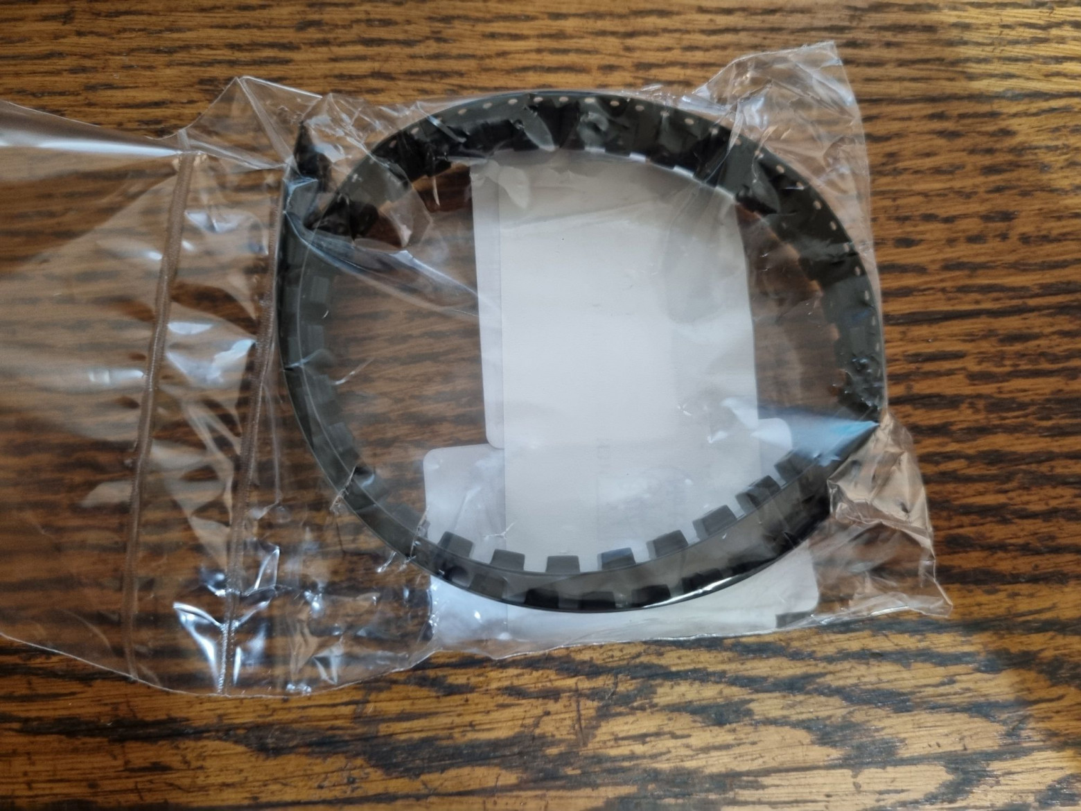
Example: the PVL-N1 call post for these stations.
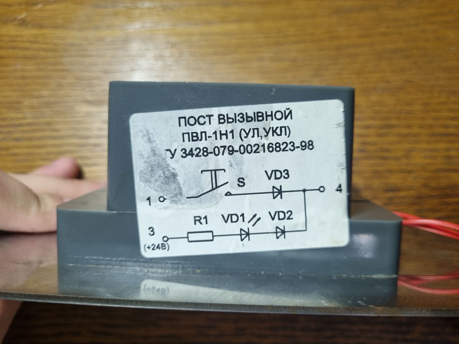
Its schematic shows contacts connected to matrix rows and columns.
Everything operates at 24V — the standard voltage for nearly all electronic elevator control systems.
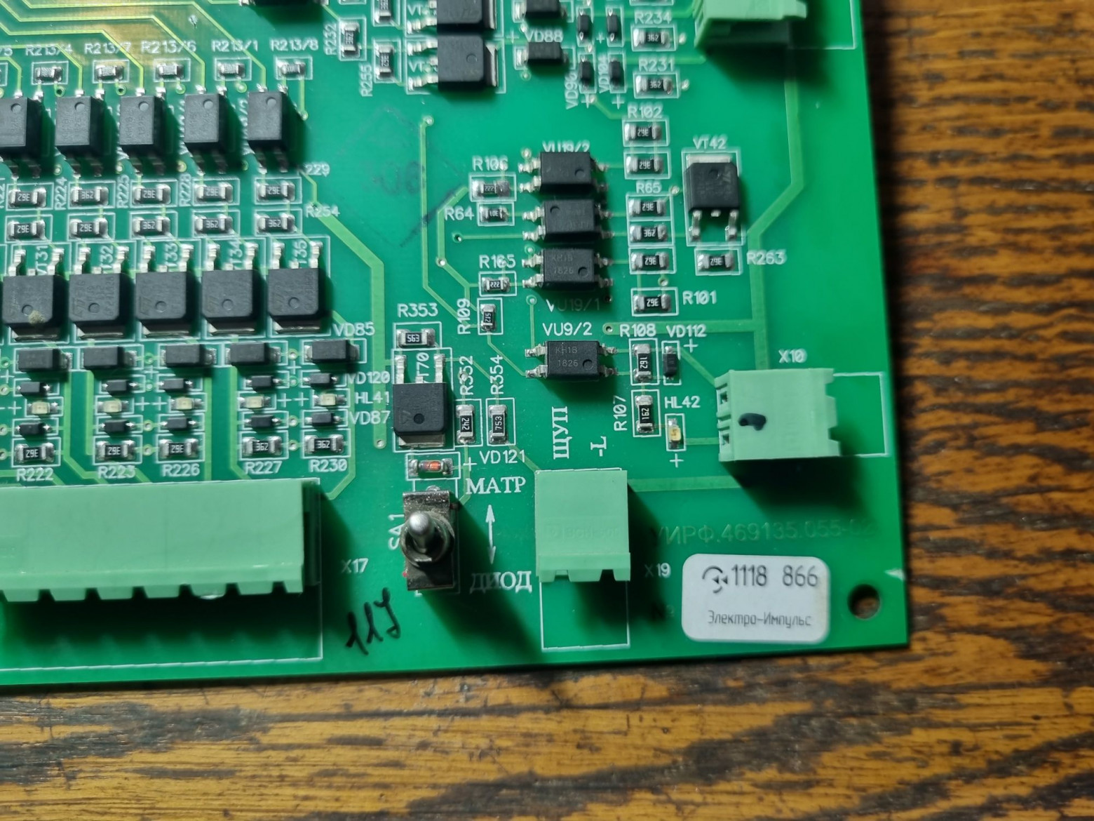
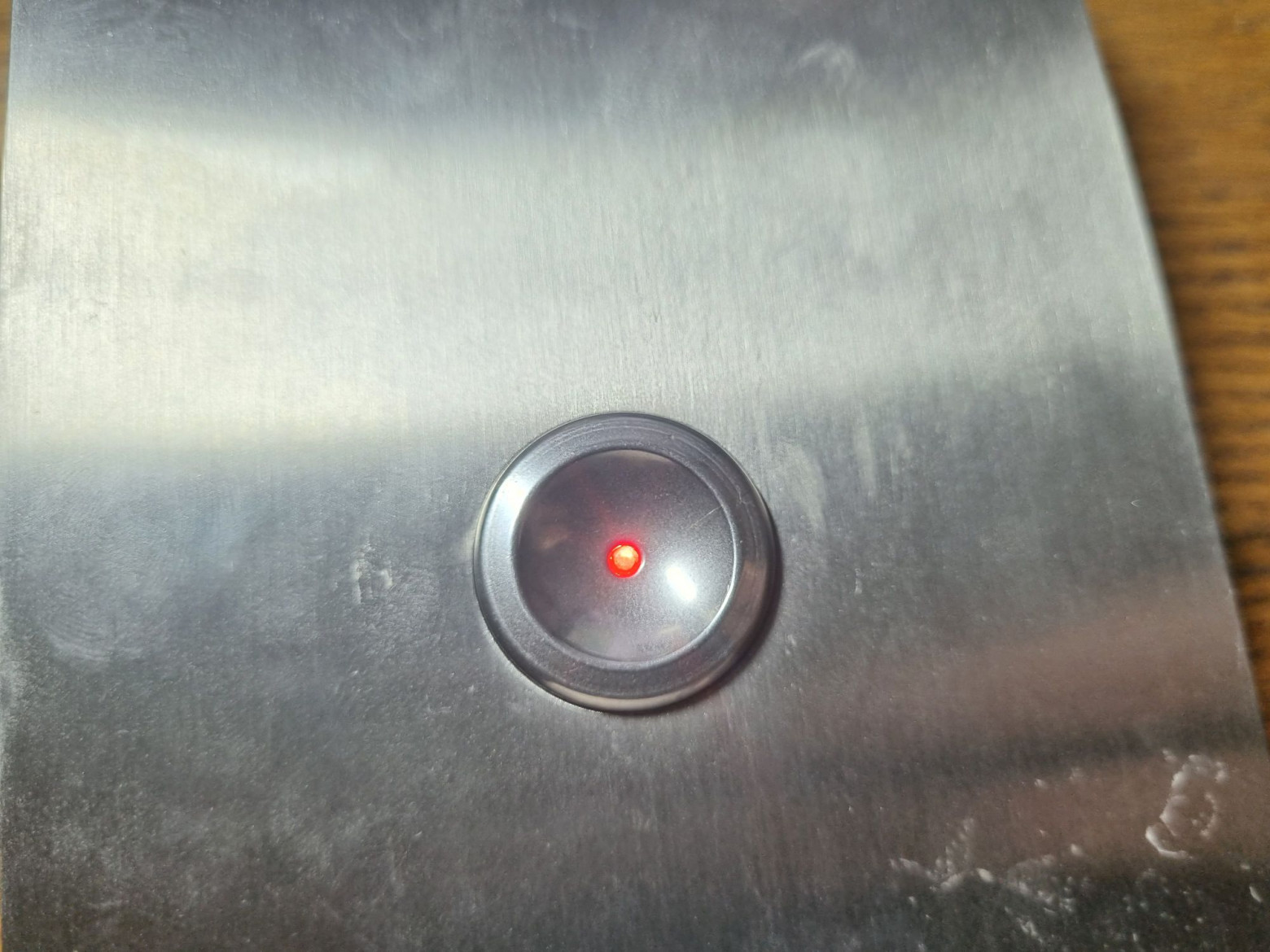
Notably, UEL boards include integrated diagnostics that allow detection of diode failures and matrix faults via a probe connected to a special contact.
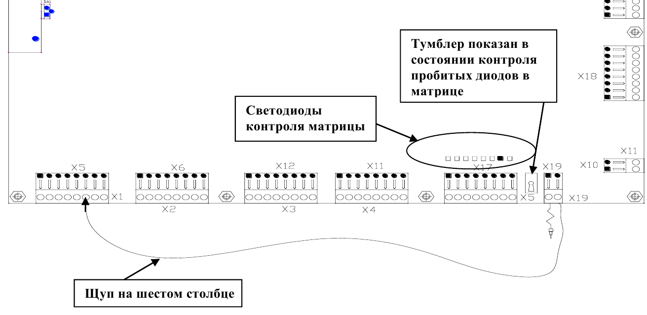
Place the probe on the faulty column; the illuminated LED row indicates the failed node.
How the MPU Works
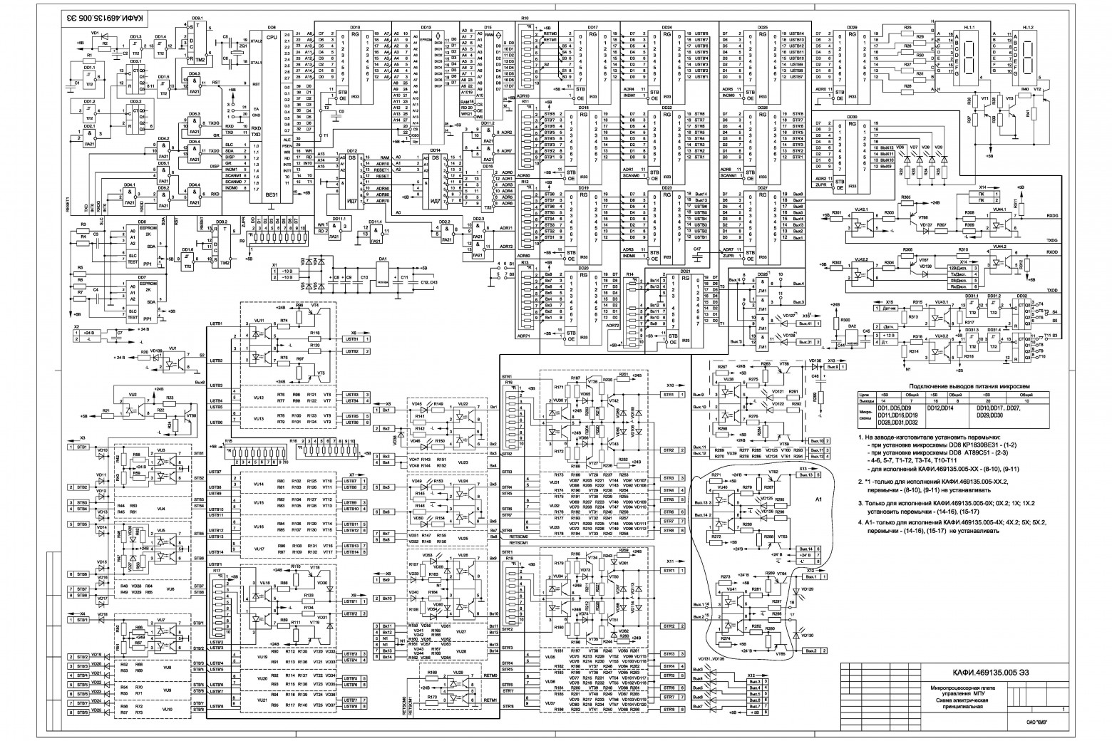
These older stations offer one significant advantage: complete schematics are publicly accessible.
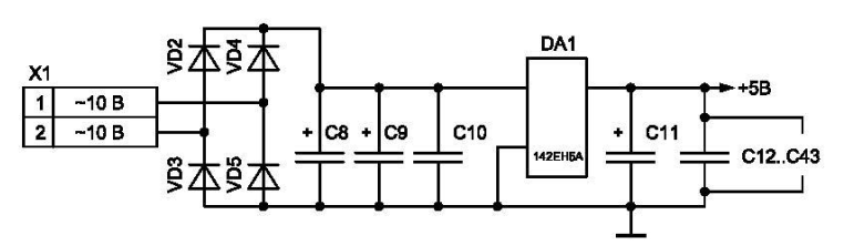
All electronics are powered from an LM7805 stabilizer. Since the board receives power from a separate transformer winding, galvanic isolation from the mains is maintained.
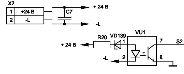
The 24V from the power supply board powers the matrix and discrete outputs. A dedicated optocoupler monitors voltage presence; its absence triggers an error.
The control microcontroller is typically a KR1830VE31 (a basic 8031 clone) in older revisions or an AT89S52 in newer ones. Settings are hardcoded in firmware. You cannot simply swap a residential building board into an office building — the microcontroller and firmware must be replaced. Special conditions like skipping specific floors demand custom firmware.
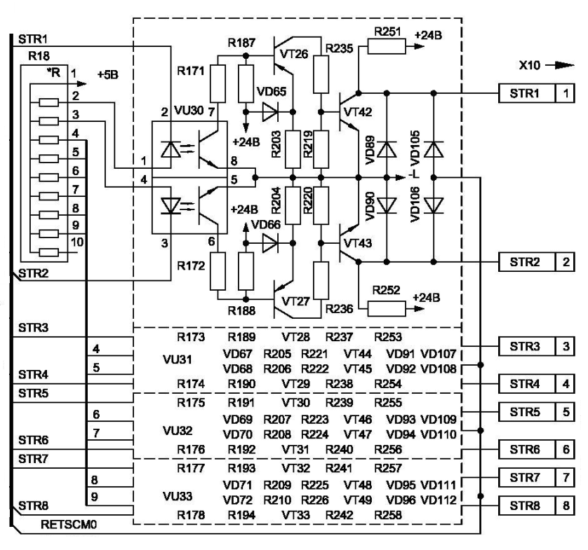
Matrix outputs incorporate optocouplers for galvanic isolation. The optoisolator signal controls a power transistor — not the matrix output directly.
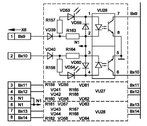
Discrete inputs (lockout circuits, cab doors, shaft doors) connect via separate optocouplers with independent common terminals, unconnected to the matrix common line. These receive approximately 110V. A notable quirk: failed indicator LEDs also disable the corresponding inputs.
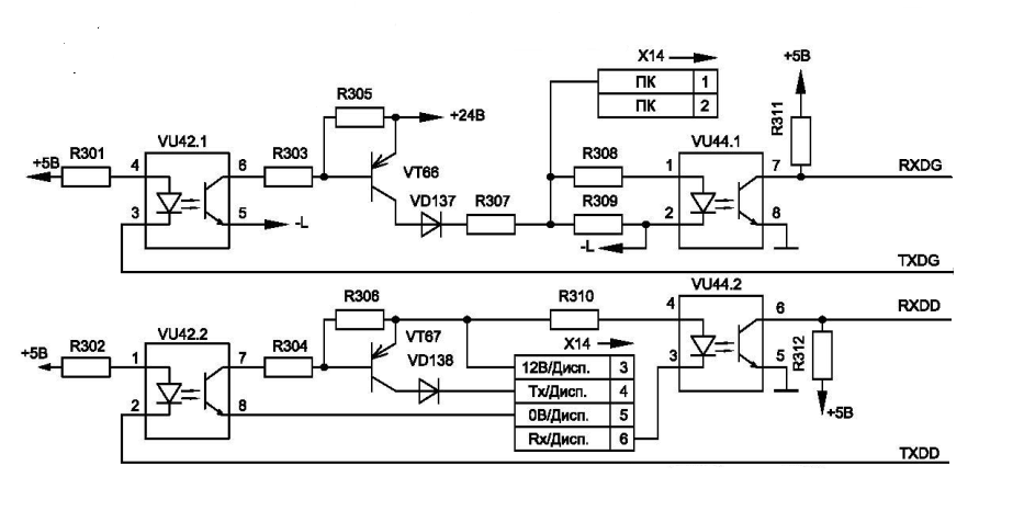
The dispatcher interface connection also includes galvanic isolation.
Sensors
Beyond call buttons and command lights, the matrix connects additional sensors. Since rapid polling keeps latency acceptable, these sensors include: cab roof detectors, door microswitches, door reversal sensors, and load sensors. The station provides three load signals:
- 15 kg — occupancy detected (someone is in the cab)
- 90% — normal operation without serving hall calls
- 110% — overload: indicator illuminates, elevator immobilized
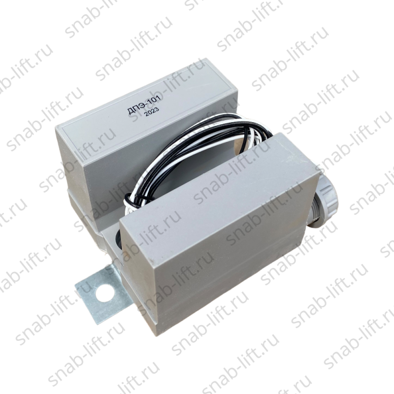
Cab roof sensors determine position. Old systems used reed switches; current systems employ inductive sensors. For reliability — preventing crashes from poor contact — sensors operate on break rather than closure. This is a critical safety principle: if a sensor or optocoupler fails unexpectedly, the elevator simply stops instead of ramming the ceiling or floor.
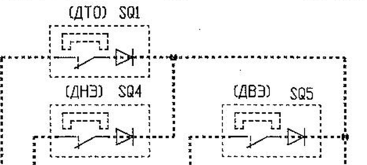
Three sensors exist: upper floor, lower floor, and precise stop.
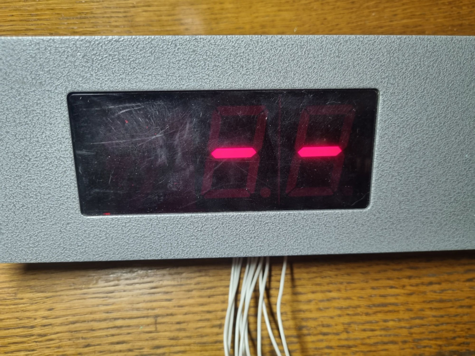
At startup, the control station cannot determine position (the display shows dashes), so it performs a correction run: the cab travels toward one extreme floor (typically top or bottom) until triggering its sensor. This resembles how a matrix printer or inkjet initializes — the print head travels until hitting its mechanical stop.
Providing a sensor signal immediately determines the cab position.
Safety Circuits
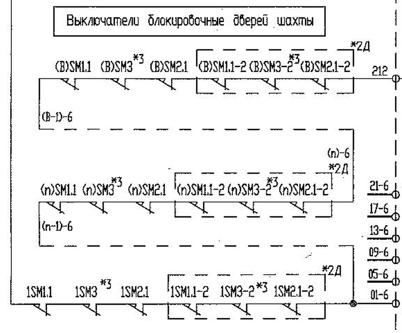
The sensors described above represent only a fraction of the elevator's safety mechanisms. Separate safety circuits (cab and shaft door microswitches) and lockout mechanisms (safety gears, rope tension monitors, and other devices) must all remain active. Any malfunction in any of these circuits prevents elevator movement.
Critically, this safety control is fully hardware-based — constructed entirely from relays and dry contacts. The microprocessor board simply monitors these signals to display errors and block operation pending a technician's arrival. Even if the entire electronic control system fails catastrophically, the mechanical and relay interlocks independently prevent the cab from moving.
What's the Bottom Line?
What appears deceptively simple at first glance proves considerably more complex in reality. The crucial advantage of this design philosophy is complete safety during any electronic failure. Should the electronics malfunction, mechanical and relay interlocks prevent cab movement. Optocouplers, protective diodes, and galvanic isolation between power, control, and safety circuits reduce failure probability substantially.
Arduino-based elevators exist in exactly one place: educational demonstrations. And they should stay there. Real elevator systems require layered safety mechanisms, galvanic isolation, redundant sensors operating on fail-safe principles, and hardware interlocks that function independently of any software. No hobbyist microcontroller platform provides these guarantees.


